
Shenzhen Just Motion Control electromechanics co., ltd
0755-26509689
7.3 manual gain adjustment
7.3.1 Basic parameters
When the automatic gain adjustment fails to achieve the desired effect, the gain can be manually fine-tuned to
optimize the effect.
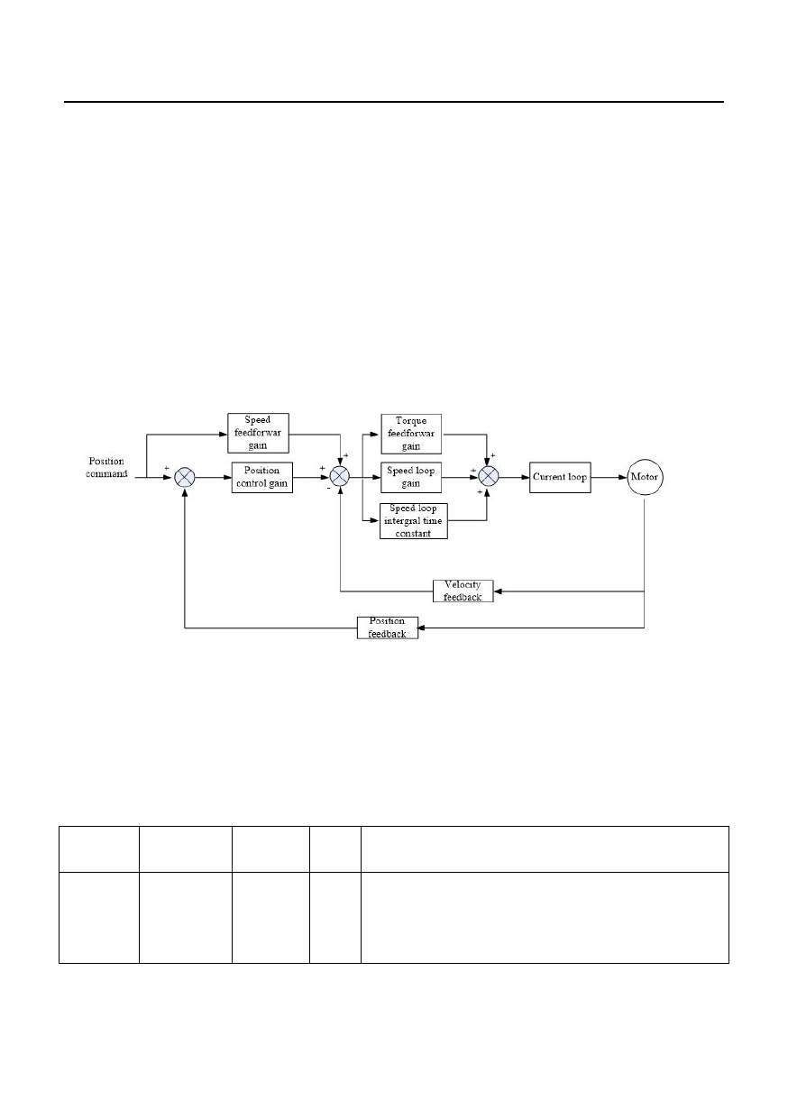
The servo system consists of three control loops, and the basic control block diagram is as follows:
The gain adjustment shall follow the sequence of inner loop and outer loop, first set the
load moment of inertia ratio P01-04, then adjust the gain of speed loop, and finally adjust the gain of position loop.
Speed loop gain: the setting value can be increased as much as possible under the condition of no
vibration and no noise, which can improve the speed following performance and speed up the
positioning time.
Speed integral constant: the smaller the set value, the faster the integral speed and the stronger
the integral effect. If the value is too small, it is easy to produce vibration and noise.
paramete
r code
Name
setting
range
sett
ing
Say it. Ming
Real-time
0: Manually adjust the rigidity.
automatic
P01-02.0
0-4
adjustment
mode
1: Standard mode automatically adjusts rigidity. In this
0
mode, parameters P02-00, P02-01, P02-10, P02-11, P02-13,
P02-14, P08-20 and P08-21 will be automatically set
65
 JAND P28 15002 DB44 AC Servo Driver User Manual")
 JAND P28 15002 DB44 AC Servo Driver User Manual")
 JAND P28 15002 DB44 AC Servo Driver User Manual")
 JAND P28 15002 DB44 AC Servo Driver User Manual")
 JAND P28 15002 DB44 AC Servo Driver User Manual")
 JAND P28 15002 DB44 AC Servo Driver User Manual")
 JAND P28 15002 DB44 AC Servo Driver User Manual")
 JAND P28 15002 DB44 AC Servo Driver User Manual")
 JAND P28 15002 DB44 AC Servo Driver User Manual")
 JAND P28 15002 DB44 AC Servo Driver User Manual")
 JAND P28 15002 DB44 AC Servo Driver User Manual")
 JAND P28 15002 DB44 AC Servo Driver User Manual")
 JAND P28 15002 DB44 AC Servo Driver User Manual")
 JAND P28 15002 DB44 AC Servo Driver User Manual")
 JAND P28 15002 DB44 AC Servo Driver User Manual")
 JAND P28 15002 DB44 AC Servo Driver User Manual")
 JAND P28 15002 DB44 AC Servo Driver User Manual")
 JAND P28 15002 DB44 AC Servo Driver User Manual")
 JAND P28 15002 DB44 AC Servo Driver User Manual")
 JAND P28 15002 DB44 AC Servo Driver User Manual")
 JAND P28 15002 DB44 AC Servo Driver User Manual")
 JAND P28 15002 DB44 AC Servo Driver User Manual")
 JAND P28 15002 DB44 AC Servo Driver User Manual")
 JAND P28 15002 DB44 AC Servo Driver User Manual")
 JAND P28 15002 DB44 AC Servo Driver User Manual")
 JAND P28 15002 DB44 AC Servo Driver User Manual")
 JAND P28 15002 DB44 AC Servo Driver User Manual")
 JAND P28 15002 DB44 AC Servo Driver User Manual")
 JAND P28 15002 DB44 AC Servo Driver User Manual")
 JAND P28 15002 DB44 AC Servo Driver User Manual")
 JAND P28 15002 DB44 AC Servo Driver User Manual")
 JAND P28 15002 DB44 AC Servo Driver User Manual")
 JAND P28 15002 DB44 AC Servo Driver User Manual")
 JAND P28 15002 DB44 AC Servo Driver User Manual")
 JAND P28 15002 DB44 AC Servo Driver User Manual")
 JAND P28 15002 DB44 AC Servo Driver User Manual")
 JAND P28 15002 DB44 AC Servo Driver User Manual")
 JAND P28 15002 DB44 AC Servo Driver User Manual")
 JAND P28 15002 DB44 AC Servo Driver User Manual")
 JAND P28 15002 DB44 AC Servo Driver User Manual")
 JAND P28 15002 DB44 AC Servo Driver User Manual")
 JAND P28 15002 DB44 AC Servo Driver User Manual")
 JAND P28 15002 DB44 AC Servo Driver User Manual")
 JAND P28 15002 DB44 AC Servo Driver User Manual")
 JAND P28 15002 DB44 AC Servo Driver User Manual")
 JAND P28 15002 DB44 AC Servo Driver User Manual")
 JAND P28 15002 DB44 AC Servo Driver User Manual")
 JAND P28 15002 DB44 AC Servo Driver User Manual")
 JAND P28 15002 DB44 AC Servo Driver User Manual")
 JAND P28 15002 DB44 AC Servo Driver User Manual")
 JAND P28 15002 DB44 AC Servo Driver User Manual")
 JAND P28 15002 DB44 AC Servo Driver User Manual")
 JAND P28 15002 DB44 AC Servo Driver User Manual")
 JAND P28 15002 DB44 AC Servo Driver User Manual")
 JAND P28 15002 DB44 AC Servo Driver User Manual")
 JAND P28 15002 DB44 AC Servo Driver User Manual")
 JAND P28 15002 DB44 AC Servo Driver User Manual")
 JAND P28 15002 DB44 AC Servo Driver User Manual")
 JAND P28 15002 DB44 AC Servo Driver User Manual")
 JAND P28 15002 DB44 AC Servo Driver User Manual")
 JAND P28 15002 DB44 AC Servo Driver User Manual")
 JAND P28 15002 DB44 AC Servo Driver User Manual")
 JAND P28 15002 DB44 AC Servo Driver User Manual")
 JAND P28 15002 DB44 AC Servo Driver User Manual")
 JAND P28 15002 DB44 AC Servo Driver User Manual")
 JAND P28 15002 DB44 AC Servo Driver User Manual")
 JAND P28 15002 DB44 AC Servo Driver User Manual")
 JAND P28 15002 DB44 AC Servo Driver User Manual")
 JAND P28 15002 DB44 AC Servo Driver User Manual")
 JAND P28 15002 DB44 AC Servo Driver User Manual")
 JAND P28 15002 DB44 AC Servo Driver User Manual")
 JAND P28 15002 DB44 AC Servo Driver User Manual")
 JAND P28 15002 DB44 AC Servo Driver User Manual")
 JAND P28 15002 DB44 AC Servo Driver User Manual")
 JAND P28 15002 DB44 AC Servo Driver User Manual")
 JAND P28 15002 DB44 AC Servo Driver User Manual")
 JAND P28 15002 DB44 AC Servo Driver User Manual")
 JAND P28 15002 DB44 AC Servo Driver User Manual")
 JAND P28 15002 DB44 AC Servo Driver User Manual")
 JAND P28 15002 DB44 AC Servo Driver User Manual")
 JAND P28 15002 DB44 AC Servo Driver User Manual")
 JAND P28 15002 DB44 AC Servo Driver User Manual")
 JAND P28 15002 DB44 AC Servo Driver User Manual")
 JAND P28 15002 DB44 AC Servo Driver User Manual")
 JAND P28 15002 DB44 AC Servo Driver User Manual")
 JAND P28 15002 DB44 AC Servo Driver User Manual")
 JAND P28 15002 DB44 AC Servo Driver User Manual")
 JAND P28 15002 DB44 AC Servo Driver User Manual")
 JAND P28 15002 DB44 AC Servo Driver User Manual")
 JAND P28 15002 DB44 AC Servo Driver User Manual")
 JAND P28 15002 DB44 AC Servo Driver User Manual")
 JAND P28 15002 DB44 AC Servo Driver User Manual")
 JAND P28 15002 DB44 AC Servo Driver User Manual")
 JAND P28 15002 DB44 AC Servo Driver User Manual")
 JAND P28 15002 DB44 AC Servo Driver User Manual")
 JAND P28 15002 DB44 AC Servo Driver User Manual")
 JAND P28 15002 DB44 AC Servo Driver User Manual")
 JAND P28 15002 DB44 AC Servo Driver User Manual")
 JAND P28 15002 DB44 AC Servo Driver User Manual")
 JAND P28 15002 DB44 AC Servo Driver User Manual")
 JAND P28 15002 DB44 AC Servo Driver User Manual")
 JAND P28 15002 DB44 AC Servo Driver User Manual")
 JAND P28 15002 DB44 AC Servo Driver User Manual")
 JAND P28 15002 DB44 AC Servo Driver User Manual")
 JAND P28 15002 DB44 AC Servo Driver User Manual")
 JAND P28 15002 DB44 AC Servo Driver User Manual")
 JAND P28 15002 DB44 AC Servo Driver User Manual")
 JAND P28 15002 DB44 AC Servo Driver User Manual")
 JAND P28 15002 DB44 AC Servo Driver User Manual")
 JAND P28 15002 DB44 AC Servo Driver User Manual")
 JAND P28 15002 DB44 AC Servo Driver User Manual")
 JAND P28 15002 DB44 AC Servo Driver User Manual")
 JAND P28 15002 DB44 AC Servo Driver User Manual")
 JAND P28 15002 DB44 AC Servo Driver User Manual")
 JAND P28 15002 DB44 AC Servo Driver User Manual")
 JAND P28 15002 DB44 AC Servo Driver User Manual")
 JAND P28 15002 DB44 AC Servo Driver User Manual")
 JAND P28 15002 DB44 AC Servo Driver User Manual")
 JAND P28 15002 DB44 AC Servo Driver User Manual")
 JAND P28 15002 DB44 AC Servo Driver User Manual")
 JAND P28 15002 DB44 AC Servo Driver User Manual")
 JAND P28 15002 DB44 AC Servo Driver User Manual")
 JAND P28 15002 DB44 AC Servo Driver User Manual")
 JAND P28 15002 DB44 AC Servo Driver User Manual")
 JAND P28 15002 DB44 AC Servo Driver User Manual")
 JAND P28 15002 DB44 AC Servo Driver User Manual")
 JAND P28 15002 DB44 AC Servo Driver User Manual")
 JAND P28 15002 DB44 AC Servo Driver User Manual")
 JAND P28 15002 DB44 AC Servo Driver User Manual")
 JAND P28 15002 DB44 AC Servo Driver User Manual")
 JAND P28 15002 DB44 AC Servo Driver User Manual")
 JAND P28 15002 DB44 AC Servo Driver User Manual")
 JAND P28 15002 DB44 AC Servo Driver User Manual")
 JAND P28 15002 DB44 AC Servo Driver User Manual")
 JAND P28 15002 DB44 AC Servo Driver User Manual")
 JAND P28 15002 DB44 AC Servo Driver User Manual")
 JAND P28 15002 DB44 AC Servo Driver User Manual")
 JAND P28 15002 DB44 AC Servo Driver User Manual")
 JAND P28 15002 DB44 AC Servo Driver User Manual")
 JAND P28 15002 DB44 AC Servo Driver User Manual")
 JAND P28 15002 DB44 AC Servo Driver User Manual")
 JAND P28 15002 DB44 AC Servo Driver User Manual")
 JAND P28 15002 DB44 AC Servo Driver User Manual")
 JAND P28 15002 DB44 AC Servo Driver User Manual")
 JAND P28 15002 DB44 AC Servo Driver User Manual")
 JAND P28 15002 DB44 AC Servo Driver User Manual")
 JAND P28 15002 DB44 AC Servo Driver User Manual")
 JAND P28 15002 DB44 AC Servo Driver User Manual")
 JAND P28 15002 DB44 AC Servo Driver User Manual")
 JAND P28 15002 DB44 AC Servo Driver User Manual")
 JAND P28 15002 DB44 AC Servo Driver User Manual")
 JAND P28 15002 DB44 AC Servo Driver User Manual")
 JAND P28 15002 DB44 AC Servo Driver User Manual")
 JAND P28 15002 DB44 AC Servo Driver User Manual")
 JAND P28 15002 DB44 AC Servo Driver User Manual")
 JAND P28 15002 DB44 AC Servo Driver User Manual")
 JAND P28 15002 DB44 AC Servo Driver User Manual")
 JAND P28 15002 DB44 AC Servo Driver User Manual")
 JAND P28 15002 DB44 AC Servo Driver User Manual")
 JAND P28 15002 DB44 AC Servo Driver User Manual")
 JAND P28 15002 DB44 AC Servo Driver User Manual")
 JAND P28 15002 DB44 AC Servo Driver User Manual")
 JAND P28 15002 DB44 AC Servo Driver User Manual")
 JAND P28 15002 DB44 AC Servo Driver User Manual")
 JAND P28 15002 DB44 AC Servo Driver User Manual")
 JAND P28 15002 DB44 AC Servo Driver User Manual")
 JAND P28 15002 DB44 AC Servo Driver User Manual")
 JAND P28 15002 DB44 AC Servo Driver User Manual")
 JAND P28 15002 DB44 AC Servo Driver User Manual")
 JAND P28 15002 DB44 AC Servo Driver User Manual")
 JAND P28 15002 DB44 AC Servo Driver User Manual")
 JAND P28 15002 DB44 AC Servo Driver User Manual")
 JAND P28 15002 DB44 AC Servo Driver User Manual")
 JAND P28 15002 DB44 AC Servo Driver User Manual")
 JAND P28 15002 DB44 AC Servo Driver User Manual")
 JAND P28 15002 DB44 AC Servo Driver User Manual")
 JAND P28 15002 DB44 AC Servo Driver User Manual")
 JAND P28 15002 DB44 AC Servo Driver User Manual")
 JAND P28 15002 DB44 AC Servo Driver User Manual")
 JAND P28 15002 DB44 AC Servo Driver User Manual")
 JAND P28 15002 DB44 AC Servo Driver User Manual")
 JAND P28 15002 DB44 AC Servo Driver User Manual")
 JAND P28 15002 DB44 AC Servo Driver User Manual")
 JAND P28 15002 DB44 AC Servo Driver User Manual")
 JAND P28 15002 DB44 AC Servo Driver User Manual")
 JAND P28 15002 DB44 AC Servo Driver User Manual")
 JAND P28 15002 DB44 AC Servo Driver User Manual")
 JAND P28 15002 DB44 AC Servo Driver User Manual")
 JAND P28 15002 DB44 AC Servo Driver User Manual")
 JAND P28 15002 DB44 AC Servo Driver User Manual")
 JAND P28 15002 DB44 AC Servo Driver User Manual")
 JAND P28 15002 DB44 AC Servo Driver User Manual")
 JAND P28 15002 DB44 AC Servo Driver User Manual")
 JAND P28 15002 DB44 AC Servo Driver User Manual")
 JAND P28 15002 DB44 AC Servo Driver User Manual")
 JAND P28 15002 DB44 AC Servo Driver User Manual")
 JAND P28 15002 DB44 AC Servo Driver User Manual")
 JAND P28 15002 DB44 AC Servo Driver User Manual")
 JAND P28 15002 DB44 AC Servo Driver User Manual")
 JAND P28 15002 DB44 AC Servo Driver User Manual")
 JAND P28 15002 DB44 AC Servo Driver User Manual")
 JAND P28 15002 DB44 AC Servo Driver User Manual")
 JAND P28 15002 DB44 AC Servo Driver User Manual")
 JAND P28 15002 DB44 AC Servo Driver User Manual")
 JAND P28 15002 DB44 AC Servo Driver User Manual")
 JAND P28 15002 DB44 AC Servo Driver User Manual")
 JAND P28 15002 DB44 AC Servo Driver User Manual")
 JAND P28 15002 DB44 AC Servo Driver User Manual")
 JAND P28 15002 DB44 AC Servo Driver User Manual")
 JAND P28 15002 DB44 AC Servo Driver User Manual")
 JAND P28 15002 DB44 AC Servo Driver User Manual")
 JAND P28 15002 DB44 AC Servo Driver User Manual")