
Shenzhen Just Motion Control electromechanics co., ltd
0755-26509689
Chapter 3 Port Description and Wiring
3.1 Port distribution of the servo driver
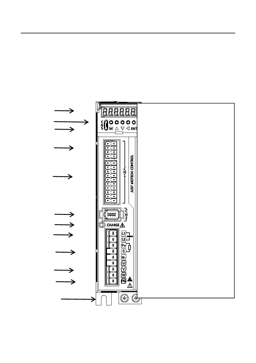
3.1.1 JAND-P28 Port distribution of the servo driver
1
1.Panel LED display
2
Display servo driver status, alarm number, parameters,
3
etc
2.Panel operation buttons
Operate the status,parameters and alarm infaomation
4
of the drive by pressing buttons
3.USB Debug
software(CN5)
5
Connect to debug software(USB communication)
4.485 communication
interface(CN1)
For 485 communication,use the corresponding port in
CH1
6
5.Input/output signal
7
port(CN1)
8
The CH1 interface is defined in the label on the side
6.Encoder lines
9
interface(CN2)
Connected motor encoder
7.CHARGE indicator light
10
If the indicator light is on, it indicates that there is high
11
voltage inside the drive. Do not touch the
8.Driver power
input(L1/L2)
12
Single-phase AC220V input
When an external resistor is used,the external resistor
is connected to P+ and C
22 10.Power cable
port(U/V/W)
Connect according to motor marking U/V/W
 JAND P28 15002 DB44 AC Servo Driver User Manual")
 JAND P28 15002 DB44 AC Servo Driver User Manual")
 JAND P28 15002 DB44 AC Servo Driver User Manual")
 JAND P28 15002 DB44 AC Servo Driver User Manual")
 JAND P28 15002 DB44 AC Servo Driver User Manual")
 JAND P28 15002 DB44 AC Servo Driver User Manual")
 JAND P28 15002 DB44 AC Servo Driver User Manual")
 JAND P28 15002 DB44 AC Servo Driver User Manual")
 JAND P28 15002 DB44 AC Servo Driver User Manual")
 JAND P28 15002 DB44 AC Servo Driver User Manual")
 JAND P28 15002 DB44 AC Servo Driver User Manual")
 JAND P28 15002 DB44 AC Servo Driver User Manual")
 JAND P28 15002 DB44 AC Servo Driver User Manual")
 JAND P28 15002 DB44 AC Servo Driver User Manual")
 JAND P28 15002 DB44 AC Servo Driver User Manual")
 JAND P28 15002 DB44 AC Servo Driver User Manual")
 JAND P28 15002 DB44 AC Servo Driver User Manual")
 JAND P28 15002 DB44 AC Servo Driver User Manual")
 JAND P28 15002 DB44 AC Servo Driver User Manual")
 JAND P28 15002 DB44 AC Servo Driver User Manual")
 JAND P28 15002 DB44 AC Servo Driver User Manual")
 JAND P28 15002 DB44 AC Servo Driver User Manual")
 JAND P28 15002 DB44 AC Servo Driver User Manual")
 JAND P28 15002 DB44 AC Servo Driver User Manual")
 JAND P28 15002 DB44 AC Servo Driver User Manual")
 JAND P28 15002 DB44 AC Servo Driver User Manual")
 JAND P28 15002 DB44 AC Servo Driver User Manual")
 JAND P28 15002 DB44 AC Servo Driver User Manual")
 JAND P28 15002 DB44 AC Servo Driver User Manual")
 JAND P28 15002 DB44 AC Servo Driver User Manual")
 JAND P28 15002 DB44 AC Servo Driver User Manual")
 JAND P28 15002 DB44 AC Servo Driver User Manual")
 JAND P28 15002 DB44 AC Servo Driver User Manual")
 JAND P28 15002 DB44 AC Servo Driver User Manual")
 JAND P28 15002 DB44 AC Servo Driver User Manual")
 JAND P28 15002 DB44 AC Servo Driver User Manual")
 JAND P28 15002 DB44 AC Servo Driver User Manual")
 JAND P28 15002 DB44 AC Servo Driver User Manual")
 JAND P28 15002 DB44 AC Servo Driver User Manual")
 JAND P28 15002 DB44 AC Servo Driver User Manual")
 JAND P28 15002 DB44 AC Servo Driver User Manual")
 JAND P28 15002 DB44 AC Servo Driver User Manual")
 JAND P28 15002 DB44 AC Servo Driver User Manual")
 JAND P28 15002 DB44 AC Servo Driver User Manual")
 JAND P28 15002 DB44 AC Servo Driver User Manual")
 JAND P28 15002 DB44 AC Servo Driver User Manual")
 JAND P28 15002 DB44 AC Servo Driver User Manual")
 JAND P28 15002 DB44 AC Servo Driver User Manual")
 JAND P28 15002 DB44 AC Servo Driver User Manual")
 JAND P28 15002 DB44 AC Servo Driver User Manual")
 JAND P28 15002 DB44 AC Servo Driver User Manual")
 JAND P28 15002 DB44 AC Servo Driver User Manual")
 JAND P28 15002 DB44 AC Servo Driver User Manual")

 JAND P28 15002 DB44 AC Servo Driver User Manual")
 JAND P28 15002 DB44 AC Servo Driver User Manual")
 JAND P28 15002 DB44 AC Servo Driver User Manual")
 JAND P28 15002 DB44 AC Servo Driver User Manual")
 JAND P28 15002 DB44 AC Servo Driver User Manual")
 JAND P28 15002 DB44 AC Servo Driver User Manual")
 JAND P28 15002 DB44 AC Servo Driver User Manual")
 JAND P28 15002 DB44 AC Servo Driver User Manual")
 JAND P28 15002 DB44 AC Servo Driver User Manual")
 JAND P28 15002 DB44 AC Servo Driver User Manual")
 JAND P28 15002 DB44 AC Servo Driver User Manual")
 JAND P28 15002 DB44 AC Servo Driver User Manual")
 JAND P28 15002 DB44 AC Servo Driver User Manual")
 JAND P28 15002 DB44 AC Servo Driver User Manual")
 JAND P28 15002 DB44 AC Servo Driver User Manual")
 JAND P28 15002 DB44 AC Servo Driver User Manual")
 JAND P28 15002 DB44 AC Servo Driver User Manual")
 JAND P28 15002 DB44 AC Servo Driver User Manual")
 JAND P28 15002 DB44 AC Servo Driver User Manual")
 JAND P28 15002 DB44 AC Servo Driver User Manual")
 JAND P28 15002 DB44 AC Servo Driver User Manual")
 JAND P28 15002 DB44 AC Servo Driver User Manual")
 JAND P28 15002 DB44 AC Servo Driver User Manual")
 JAND P28 15002 DB44 AC Servo Driver User Manual")
 JAND P28 15002 DB44 AC Servo Driver User Manual")
 JAND P28 15002 DB44 AC Servo Driver User Manual")
 JAND P28 15002 DB44 AC Servo Driver User Manual")
 JAND P28 15002 DB44 AC Servo Driver User Manual")
 JAND P28 15002 DB44 AC Servo Driver User Manual")
 JAND P28 15002 DB44 AC Servo Driver User Manual")
 JAND P28 15002 DB44 AC Servo Driver User Manual")
 JAND P28 15002 DB44 AC Servo Driver User Manual")
 JAND P28 15002 DB44 AC Servo Driver User Manual")
 JAND P28 15002 DB44 AC Servo Driver User Manual")
 JAND P28 15002 DB44 AC Servo Driver User Manual")
 JAND P28 15002 DB44 AC Servo Driver User Manual")
 JAND P28 15002 DB44 AC Servo Driver User Manual")
 JAND P28 15002 DB44 AC Servo Driver User Manual")
 JAND P28 15002 DB44 AC Servo Driver User Manual")
 JAND P28 15002 DB44 AC Servo Driver User Manual")
 JAND P28 15002 DB44 AC Servo Driver User Manual")
 JAND P28 15002 DB44 AC Servo Driver User Manual")
 JAND P28 15002 DB44 AC Servo Driver User Manual")
 JAND P28 15002 DB44 AC Servo Driver User Manual")
 JAND P28 15002 DB44 AC Servo Driver User Manual")
 JAND P28 15002 DB44 AC Servo Driver User Manual")
 JAND P28 15002 DB44 AC Servo Driver User Manual")
 JAND P28 15002 DB44 AC Servo Driver User Manual")
 JAND P28 15002 DB44 AC Servo Driver User Manual")
 JAND P28 15002 DB44 AC Servo Driver User Manual")
 JAND P28 15002 DB44 AC Servo Driver User Manual")
 JAND P28 15002 DB44 AC Servo Driver User Manual")
 JAND P28 15002 DB44 AC Servo Driver User Manual")
 JAND P28 15002 DB44 AC Servo Driver User Manual")
 JAND P28 15002 DB44 AC Servo Driver User Manual")
 JAND P28 15002 DB44 AC Servo Driver User Manual")
 JAND P28 15002 DB44 AC Servo Driver User Manual")
 JAND P28 15002 DB44 AC Servo Driver User Manual")
 JAND P28 15002 DB44 AC Servo Driver User Manual")
 JAND P28 15002 DB44 AC Servo Driver User Manual")
 JAND P28 15002 DB44 AC Servo Driver User Manual")
 JAND P28 15002 DB44 AC Servo Driver User Manual")
 JAND P28 15002 DB44 AC Servo Driver User Manual")
 JAND P28 15002 DB44 AC Servo Driver User Manual")
 JAND P28 15002 DB44 AC Servo Driver User Manual")
 JAND P28 15002 DB44 AC Servo Driver User Manual")
 JAND P28 15002 DB44 AC Servo Driver User Manual")
 JAND P28 15002 DB44 AC Servo Driver User Manual")
 JAND P28 15002 DB44 AC Servo Driver User Manual")
 JAND P28 15002 DB44 AC Servo Driver User Manual")
 JAND P28 15002 DB44 AC Servo Driver User Manual")
 JAND P28 15002 DB44 AC Servo Driver User Manual")
 JAND P28 15002 DB44 AC Servo Driver User Manual")
 JAND P28 15002 DB44 AC Servo Driver User Manual")
 JAND P28 15002 DB44 AC Servo Driver User Manual")
 JAND P28 15002 DB44 AC Servo Driver User Manual")
 JAND P28 15002 DB44 AC Servo Driver User Manual")
 JAND P28 15002 DB44 AC Servo Driver User Manual")
 JAND P28 15002 DB44 AC Servo Driver User Manual")
 JAND P28 15002 DB44 AC Servo Driver User Manual")
 JAND P28 15002 DB44 AC Servo Driver User Manual")
 JAND P28 15002 DB44 AC Servo Driver User Manual")
 JAND P28 15002 DB44 AC Servo Driver User Manual")
 JAND P28 15002 DB44 AC Servo Driver User Manual")
 JAND P28 15002 DB44 AC Servo Driver User Manual")
 JAND P28 15002 DB44 AC Servo Driver User Manual")
 JAND P28 15002 DB44 AC Servo Driver User Manual")
 JAND P28 15002 DB44 AC Servo Driver User Manual")
 JAND P28 15002 DB44 AC Servo Driver User Manual")
 JAND P28 15002 DB44 AC Servo Driver User Manual")
 JAND P28 15002 DB44 AC Servo Driver User Manual")
 JAND P28 15002 DB44 AC Servo Driver User Manual")
 JAND P28 15002 DB44 AC Servo Driver User Manual")
 JAND P28 15002 DB44 AC Servo Driver User Manual")
 JAND P28 15002 DB44 AC Servo Driver User Manual")
 JAND P28 15002 DB44 AC Servo Driver User Manual")
 JAND P28 15002 DB44 AC Servo Driver User Manual")
 JAND P28 15002 DB44 AC Servo Driver User Manual")
 JAND P28 15002 DB44 AC Servo Driver User Manual")
 JAND P28 15002 DB44 AC Servo Driver User Manual")
 JAND P28 15002 DB44 AC Servo Driver User Manual")
 JAND P28 15002 DB44 AC Servo Driver User Manual")
 JAND P28 15002 DB44 AC Servo Driver User Manual")
 JAND P28 15002 DB44 AC Servo Driver User Manual")
 JAND P28 15002 DB44 AC Servo Driver User Manual")
 JAND P28 15002 DB44 AC Servo Driver User Manual")
 JAND P28 15002 DB44 AC Servo Driver User Manual")
 JAND P28 15002 DB44 AC Servo Driver User Manual")
 JAND P28 15002 DB44 AC Servo Driver User Manual")
 JAND P28 15002 DB44 AC Servo Driver User Manual")
 JAND P28 15002 DB44 AC Servo Driver User Manual")
 JAND P28 15002 DB44 AC Servo Driver User Manual")
 JAND P28 15002 DB44 AC Servo Driver User Manual")
 JAND P28 15002 DB44 AC Servo Driver User Manual")
 JAND P28 15002 DB44 AC Servo Driver User Manual")
 JAND P28 15002 DB44 AC Servo Driver User Manual")
 JAND P28 15002 DB44 AC Servo Driver User Manual")
 JAND P28 15002 DB44 AC Servo Driver User Manual")
 JAND P28 15002 DB44 AC Servo Driver User Manual")
 JAND P28 15002 DB44 AC Servo Driver User Manual")
 JAND P28 15002 DB44 AC Servo Driver User Manual")
 JAND P28 15002 DB44 AC Servo Driver User Manual")
 JAND P28 15002 DB44 AC Servo Driver User Manual")
 JAND P28 15002 DB44 AC Servo Driver User Manual")
 JAND P28 15002 DB44 AC Servo Driver User Manual")
 JAND P28 15002 DB44 AC Servo Driver User Manual")
 JAND P28 15002 DB44 AC Servo Driver User Manual")
 JAND P28 15002 DB44 AC Servo Driver User Manual")
 JAND P28 15002 DB44 AC Servo Driver User Manual")
 JAND P28 15002 DB44 AC Servo Driver User Manual")
 JAND P28 15002 DB44 AC Servo Driver User Manual")
 JAND P28 15002 DB44 AC Servo Driver User Manual")
 JAND P28 15002 DB44 AC Servo Driver User Manual")
 JAND P28 15002 DB44 AC Servo Driver User Manual")
 JAND P28 15002 DB44 AC Servo Driver User Manual")
 JAND P28 15002 DB44 AC Servo Driver User Manual")
 JAND P28 15002 DB44 AC Servo Driver User Manual")
 JAND P28 15002 DB44 AC Servo Driver User Manual")
 JAND P28 15002 DB44 AC Servo Driver User Manual")
 JAND P28 15002 DB44 AC Servo Driver User Manual")
 JAND P28 15002 DB44 AC Servo Driver User Manual")
 JAND P28 15002 DB44 AC Servo Driver User Manual")
 JAND P28 15002 DB44 AC Servo Driver User Manual")
 JAND P28 15002 DB44 AC Servo Driver User Manual")
 JAND P28 15002 DB44 AC Servo Driver User Manual")
 JAND P28 15002 DB44 AC Servo Driver User Manual")
 JAND P28 15002 DB44 AC Servo Driver User Manual")
 JAND P28 15002 DB44 AC Servo Driver User Manual")
 JAND P28 15002 DB44 AC Servo Driver User Manual")
 JAND P28 15002 DB44 AC Servo Driver User Manual")
 JAND P28 15002 DB44 AC Servo Driver User Manual")
 JAND P28 15002 DB44 AC Servo Driver User Manual")
 JAND P28 15002 DB44 AC Servo Driver User Manual")
 JAND P28 15002 DB44 AC Servo Driver User Manual")
 JAND P28 15002 DB44 AC Servo Driver User Manual")
 JAND P28 15002 DB44 AC Servo Driver User Manual")
 JAND P28 15002 DB44 AC Servo Driver User Manual")
 JAND P28 15002 DB44 AC Servo Driver User Manual")