
Shenzhen Just Motion Control electromechanics co., ltd
0755-26509689
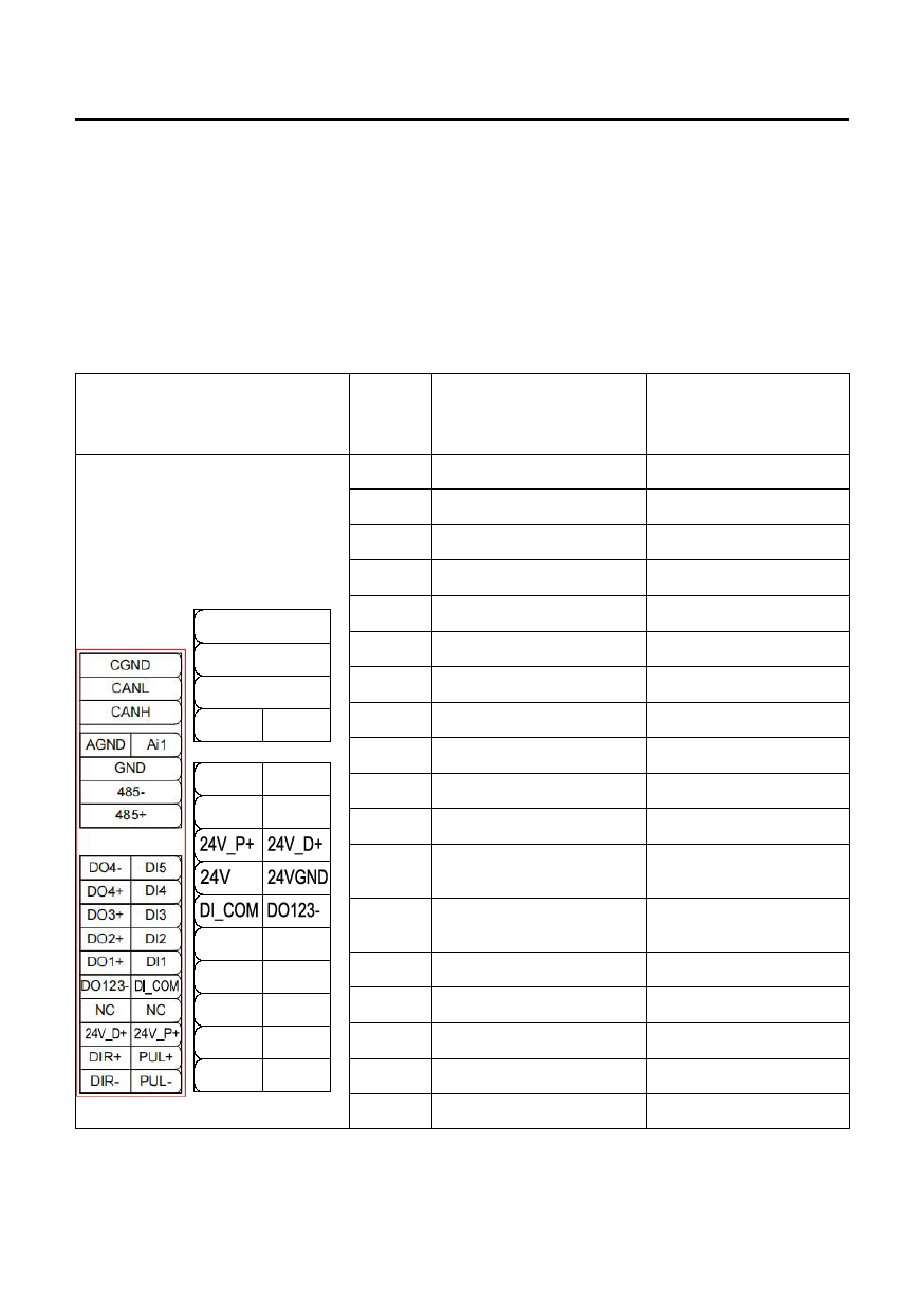
3.2 Servo drive CN1 control port description
3.2.1JAND-P28 Servo Driver CN1 Control Port Definition
The upper control and driver connection interface is used for the upper computer to control the driver and the driver
feedback output
CN1 pin schematic
485+
485-
GND
Ai1 AGND
PUL- DIR-
PUL+ DIR+
DI1 DO1+
DI2 DO2+
DI3 DO3+
DI4 DO4+
DI5 DO4-
mark
numbe
r
485+
definition
485 Signal +
standard voltage
485+
485-
485signals-
485-
GND
signal ground
signal ground
Ai1
analog control positive
±10VDC input
AGND
analogously
24V_P+ 24V pulse input positive
PUL+
5V pulse input positive
PUL-
pulse negative
24V_D+ 24V direction input positive
DIR+ 5V direction input positive
DIR-
negative direction
simulatively
24V signal
5V signal
pulse negative
24V signal
5V signal
negative direction
24V
24VGND
DI_COM
24V output (used as external
I/O)
24V output ground (used as
external I/O)
input common
Maximum allowable output
current 100mA
Maximum allowable output
current 100mA
24V/GND
DI1
Digital Input 1
GND/24V
DI2
Digital Input 2
GND/24V
DI3
Digital Input 3
GND/24V
DI4
Digital Input 4
GND/24V
24
 JAND P28 15002 DB44 AC Servo Driver User Manual")
 JAND P28 15002 DB44 AC Servo Driver User Manual")
 JAND P28 15002 DB44 AC Servo Driver User Manual")
 JAND P28 15002 DB44 AC Servo Driver User Manual")
 JAND P28 15002 DB44 AC Servo Driver User Manual")
 JAND P28 15002 DB44 AC Servo Driver User Manual")
 JAND P28 15002 DB44 AC Servo Driver User Manual")
 JAND P28 15002 DB44 AC Servo Driver User Manual")
 JAND P28 15002 DB44 AC Servo Driver User Manual")
 JAND P28 15002 DB44 AC Servo Driver User Manual")
 JAND P28 15002 DB44 AC Servo Driver User Manual")
 JAND P28 15002 DB44 AC Servo Driver User Manual")
 JAND P28 15002 DB44 AC Servo Driver User Manual")
 JAND P28 15002 DB44 AC Servo Driver User Manual")
 JAND P28 15002 DB44 AC Servo Driver User Manual")
 JAND P28 15002 DB44 AC Servo Driver User Manual")
 JAND P28 15002 DB44 AC Servo Driver User Manual")
 JAND P28 15002 DB44 AC Servo Driver User Manual")
 JAND P28 15002 DB44 AC Servo Driver User Manual")
 JAND P28 15002 DB44 AC Servo Driver User Manual")
 JAND P28 15002 DB44 AC Servo Driver User Manual")
 JAND P28 15002 DB44 AC Servo Driver User Manual")
 JAND P28 15002 DB44 AC Servo Driver User Manual")
 JAND P28 15002 DB44 AC Servo Driver User Manual")
 JAND P28 15002 DB44 AC Servo Driver User Manual")
 JAND P28 15002 DB44 AC Servo Driver User Manual")
 JAND P28 15002 DB44 AC Servo Driver User Manual")
 JAND P28 15002 DB44 AC Servo Driver User Manual")
 JAND P28 15002 DB44 AC Servo Driver User Manual")
 JAND P28 15002 DB44 AC Servo Driver User Manual")
 JAND P28 15002 DB44 AC Servo Driver User Manual")
 JAND P28 15002 DB44 AC Servo Driver User Manual")
 JAND P28 15002 DB44 AC Servo Driver User Manual")
 JAND P28 15002 DB44 AC Servo Driver User Manual")
 JAND P28 15002 DB44 AC Servo Driver User Manual")
 JAND P28 15002 DB44 AC Servo Driver User Manual")
 JAND P28 15002 DB44 AC Servo Driver User Manual")
 JAND P28 15002 DB44 AC Servo Driver User Manual")
 JAND P28 15002 DB44 AC Servo Driver User Manual")
 JAND P28 15002 DB44 AC Servo Driver User Manual")
 JAND P28 15002 DB44 AC Servo Driver User Manual")
 JAND P28 15002 DB44 AC Servo Driver User Manual")
 JAND P28 15002 DB44 AC Servo Driver User Manual")
 JAND P28 15002 DB44 AC Servo Driver User Manual")
 JAND P28 15002 DB44 AC Servo Driver User Manual")
 JAND P28 15002 DB44 AC Servo Driver User Manual")
 JAND P28 15002 DB44 AC Servo Driver User Manual")
 JAND P28 15002 DB44 AC Servo Driver User Manual")
 JAND P28 15002 DB44 AC Servo Driver User Manual")
 JAND P28 15002 DB44 AC Servo Driver User Manual")
 JAND P28 15002 DB44 AC Servo Driver User Manual")
 JAND P28 15002 DB44 AC Servo Driver User Manual")
 JAND P28 15002 DB44 AC Servo Driver User Manual")

 JAND P28 15002 DB44 AC Servo Driver User Manual")
 JAND P28 15002 DB44 AC Servo Driver User Manual")
 JAND P28 15002 DB44 AC Servo Driver User Manual")
 JAND P28 15002 DB44 AC Servo Driver User Manual")
 JAND P28 15002 DB44 AC Servo Driver User Manual")
 JAND P28 15002 DB44 AC Servo Driver User Manual")
 JAND P28 15002 DB44 AC Servo Driver User Manual")
 JAND P28 15002 DB44 AC Servo Driver User Manual")
 JAND P28 15002 DB44 AC Servo Driver User Manual")
 JAND P28 15002 DB44 AC Servo Driver User Manual")
 JAND P28 15002 DB44 AC Servo Driver User Manual")
 JAND P28 15002 DB44 AC Servo Driver User Manual")
 JAND P28 15002 DB44 AC Servo Driver User Manual")
 JAND P28 15002 DB44 AC Servo Driver User Manual")
 JAND P28 15002 DB44 AC Servo Driver User Manual")
 JAND P28 15002 DB44 AC Servo Driver User Manual")
 JAND P28 15002 DB44 AC Servo Driver User Manual")
 JAND P28 15002 DB44 AC Servo Driver User Manual")
 JAND P28 15002 DB44 AC Servo Driver User Manual")
 JAND P28 15002 DB44 AC Servo Driver User Manual")
 JAND P28 15002 DB44 AC Servo Driver User Manual")
 JAND P28 15002 DB44 AC Servo Driver User Manual")
 JAND P28 15002 DB44 AC Servo Driver User Manual")
 JAND P28 15002 DB44 AC Servo Driver User Manual")
 JAND P28 15002 DB44 AC Servo Driver User Manual")
 JAND P28 15002 DB44 AC Servo Driver User Manual")
 JAND P28 15002 DB44 AC Servo Driver User Manual")
 JAND P28 15002 DB44 AC Servo Driver User Manual")
 JAND P28 15002 DB44 AC Servo Driver User Manual")
 JAND P28 15002 DB44 AC Servo Driver User Manual")
 JAND P28 15002 DB44 AC Servo Driver User Manual")
 JAND P28 15002 DB44 AC Servo Driver User Manual")
 JAND P28 15002 DB44 AC Servo Driver User Manual")
 JAND P28 15002 DB44 AC Servo Driver User Manual")
 JAND P28 15002 DB44 AC Servo Driver User Manual")
 JAND P28 15002 DB44 AC Servo Driver User Manual")
 JAND P28 15002 DB44 AC Servo Driver User Manual")
 JAND P28 15002 DB44 AC Servo Driver User Manual")
 JAND P28 15002 DB44 AC Servo Driver User Manual")
 JAND P28 15002 DB44 AC Servo Driver User Manual")
 JAND P28 15002 DB44 AC Servo Driver User Manual")
 JAND P28 15002 DB44 AC Servo Driver User Manual")
 JAND P28 15002 DB44 AC Servo Driver User Manual")
 JAND P28 15002 DB44 AC Servo Driver User Manual")
 JAND P28 15002 DB44 AC Servo Driver User Manual")
 JAND P28 15002 DB44 AC Servo Driver User Manual")
 JAND P28 15002 DB44 AC Servo Driver User Manual")
 JAND P28 15002 DB44 AC Servo Driver User Manual")
 JAND P28 15002 DB44 AC Servo Driver User Manual")
 JAND P28 15002 DB44 AC Servo Driver User Manual")
 JAND P28 15002 DB44 AC Servo Driver User Manual")
 JAND P28 15002 DB44 AC Servo Driver User Manual")
 JAND P28 15002 DB44 AC Servo Driver User Manual")
 JAND P28 15002 DB44 AC Servo Driver User Manual")
 JAND P28 15002 DB44 AC Servo Driver User Manual")
 JAND P28 15002 DB44 AC Servo Driver User Manual")
 JAND P28 15002 DB44 AC Servo Driver User Manual")
 JAND P28 15002 DB44 AC Servo Driver User Manual")
 JAND P28 15002 DB44 AC Servo Driver User Manual")
 JAND P28 15002 DB44 AC Servo Driver User Manual")
 JAND P28 15002 DB44 AC Servo Driver User Manual")
 JAND P28 15002 DB44 AC Servo Driver User Manual")
 JAND P28 15002 DB44 AC Servo Driver User Manual")
 JAND P28 15002 DB44 AC Servo Driver User Manual")
 JAND P28 15002 DB44 AC Servo Driver User Manual")
 JAND P28 15002 DB44 AC Servo Driver User Manual")
 JAND P28 15002 DB44 AC Servo Driver User Manual")
 JAND P28 15002 DB44 AC Servo Driver User Manual")
 JAND P28 15002 DB44 AC Servo Driver User Manual")
 JAND P28 15002 DB44 AC Servo Driver User Manual")
 JAND P28 15002 DB44 AC Servo Driver User Manual")
 JAND P28 15002 DB44 AC Servo Driver User Manual")
 JAND P28 15002 DB44 AC Servo Driver User Manual")
 JAND P28 15002 DB44 AC Servo Driver User Manual")
 JAND P28 15002 DB44 AC Servo Driver User Manual")
 JAND P28 15002 DB44 AC Servo Driver User Manual")
 JAND P28 15002 DB44 AC Servo Driver User Manual")
 JAND P28 15002 DB44 AC Servo Driver User Manual")
 JAND P28 15002 DB44 AC Servo Driver User Manual")
 JAND P28 15002 DB44 AC Servo Driver User Manual")
 JAND P28 15002 DB44 AC Servo Driver User Manual")
 JAND P28 15002 DB44 AC Servo Driver User Manual")
 JAND P28 15002 DB44 AC Servo Driver User Manual")
 JAND P28 15002 DB44 AC Servo Driver User Manual")
 JAND P28 15002 DB44 AC Servo Driver User Manual")
 JAND P28 15002 DB44 AC Servo Driver User Manual")
 JAND P28 15002 DB44 AC Servo Driver User Manual")
 JAND P28 15002 DB44 AC Servo Driver User Manual")
 JAND P28 15002 DB44 AC Servo Driver User Manual")
 JAND P28 15002 DB44 AC Servo Driver User Manual")
 JAND P28 15002 DB44 AC Servo Driver User Manual")
 JAND P28 15002 DB44 AC Servo Driver User Manual")
 JAND P28 15002 DB44 AC Servo Driver User Manual")
 JAND P28 15002 DB44 AC Servo Driver User Manual")
 JAND P28 15002 DB44 AC Servo Driver User Manual")
 JAND P28 15002 DB44 AC Servo Driver User Manual")
 JAND P28 15002 DB44 AC Servo Driver User Manual")
 JAND P28 15002 DB44 AC Servo Driver User Manual")
 JAND P28 15002 DB44 AC Servo Driver User Manual")
 JAND P28 15002 DB44 AC Servo Driver User Manual")
 JAND P28 15002 DB44 AC Servo Driver User Manual")
 JAND P28 15002 DB44 AC Servo Driver User Manual")
 JAND P28 15002 DB44 AC Servo Driver User Manual")
 JAND P28 15002 DB44 AC Servo Driver User Manual")
 JAND P28 15002 DB44 AC Servo Driver User Manual")
 JAND P28 15002 DB44 AC Servo Driver User Manual")
 JAND P28 15002 DB44 AC Servo Driver User Manual")
 JAND P28 15002 DB44 AC Servo Driver User Manual")
 JAND P28 15002 DB44 AC Servo Driver User Manual")
 JAND P28 15002 DB44 AC Servo Driver User Manual")
 JAND P28 15002 DB44 AC Servo Driver User Manual")
 JAND P28 15002 DB44 AC Servo Driver User Manual")
 JAND P28 15002 DB44 AC Servo Driver User Manual")
 JAND P28 15002 DB44 AC Servo Driver User Manual")
 JAND P28 15002 DB44 AC Servo Driver User Manual")
 JAND P28 15002 DB44 AC Servo Driver User Manual")
 JAND P28 15002 DB44 AC Servo Driver User Manual")
 JAND P28 15002 DB44 AC Servo Driver User Manual")
 JAND P28 15002 DB44 AC Servo Driver User Manual")
 JAND P28 15002 DB44 AC Servo Driver User Manual")
 JAND P28 15002 DB44 AC Servo Driver User Manual")
 JAND P28 15002 DB44 AC Servo Driver User Manual")
 JAND P28 15002 DB44 AC Servo Driver User Manual")
 JAND P28 15002 DB44 AC Servo Driver User Manual")
 JAND P28 15002 DB44 AC Servo Driver User Manual")
 JAND P28 15002 DB44 AC Servo Driver User Manual")
 JAND P28 15002 DB44 AC Servo Driver User Manual")
 JAND P28 15002 DB44 AC Servo Driver User Manual")
 JAND P28 15002 DB44 AC Servo Driver User Manual")
 JAND P28 15002 DB44 AC Servo Driver User Manual")
 JAND P28 15002 DB44 AC Servo Driver User Manual")
 JAND P28 15002 DB44 AC Servo Driver User Manual")
 JAND P28 15002 DB44 AC Servo Driver User Manual")
 JAND P28 15002 DB44 AC Servo Driver User Manual")
 JAND P28 15002 DB44 AC Servo Driver User Manual")
 JAND P28 15002 DB44 AC Servo Driver User Manual")
 JAND P28 15002 DB44 AC Servo Driver User Manual")
 JAND P28 15002 DB44 AC Servo Driver User Manual")
 JAND P28 15002 DB44 AC Servo Driver User Manual")
 JAND P28 15002 DB44 AC Servo Driver User Manual")
 JAND P28 15002 DB44 AC Servo Driver User Manual")
 JAND P28 15002 DB44 AC Servo Driver User Manual")
 JAND P28 15002 DB44 AC Servo Driver User Manual")
 JAND P28 15002 DB44 AC Servo Driver User Manual")
 JAND P28 15002 DB44 AC Servo Driver User Manual")
 JAND P28 15002 DB44 AC Servo Driver User Manual")
 JAND P28 15002 DB44 AC Servo Driver User Manual")
 JAND P28 15002 DB44 AC Servo Driver User Manual")
 JAND P28 15002 DB44 AC Servo Driver User Manual")
 JAND P28 15002 DB44 AC Servo Driver User Manual")
 JAND P28 15002 DB44 AC Servo Driver User Manual")
 JAND P28 15002 DB44 AC Servo Driver User Manual")
 JAND P28 15002 DB44 AC Servo Driver User Manual")
 JAND P28 15002 DB44 AC Servo Driver User Manual")
 JAND P28 15002 DB44 AC Servo Driver User Manual")
 JAND P28 15002 DB44 AC Servo Driver User Manual")
 JAND P28 15002 DB44 AC Servo Driver User Manual")
 JAND P28 15002 DB44 AC Servo Driver User Manual")