
Chapter 3: Cutting function
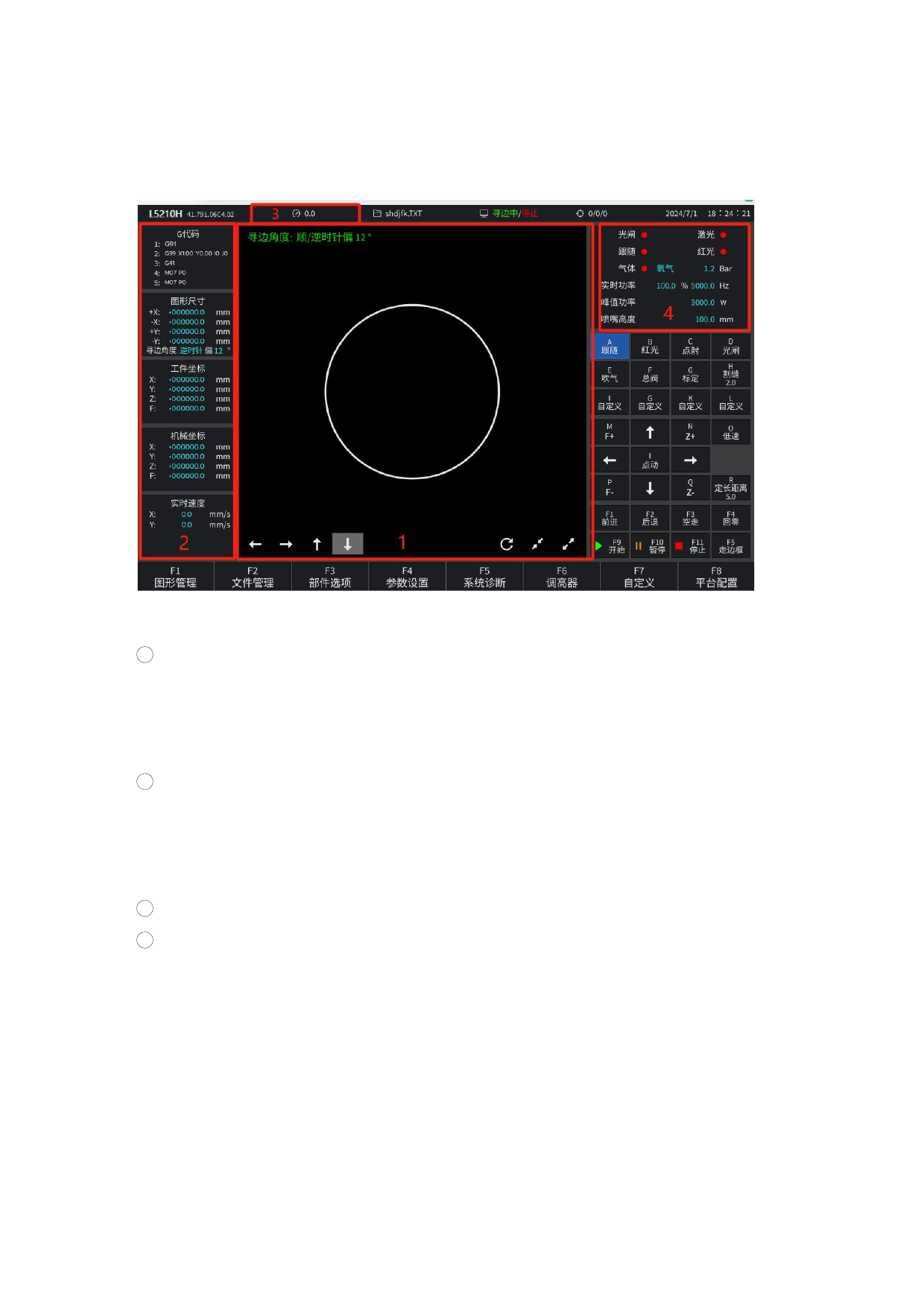
Under the main interface, it is the real-time cutting interface, as shown in
Figure 3.1.
Figure 3.1 Cutting function interface
1 Displays the cutting trace of the current processed piece. The actual outline
of the piece is displayed simultaneously with the outline with the kerf. (The green
line is the actual outline of the cutting piece, and the blue line is the cutting
track with kerf. When cutting, the center of the torch will cut along the blue line.)
2 Displays the G code currently being processed, the actual running speed of XY
and the motion coordinate value of the current cutting torch in the process of
processing, the G code display area shows the current line and the next row, which
is not displayed during the cutting operation process, only after pause.
3 Display the current processing speed.
4 Display the real-time status, light switch, gas, and real-time power and nozzle
height during processing data.
X: It represents the absolute coordinate of X where the torch is currently cut.
Y: It represents the absolute coordinate of Y where the torch is currently cut.
Under the cutting interface:
Press [X]: Forward button, the forward / backward speed modification needs to be
modified in the global parameters.
Press [Y]: Back button, the forward / back speed modification needs to be modified
in the global parameters.
110
 RAYCUT-Lite L5210H CNC Laser Cutting Controller Manual")
 RAYCUT-Lite L5210H CNC Laser Cutting Controller Manual")
 RAYCUT-Lite L5210H CNC Laser Cutting Controller Manual")
 RAYCUT-Lite L5210H CNC Laser Cutting Controller Manual")
 RAYCUT-Lite L5210H CNC Laser Cutting Controller Manual")
 RAYCUT-Lite L5210H CNC Laser Cutting Controller Manual")
 RAYCUT-Lite L5210H CNC Laser Cutting Controller Manual")
 RAYCUT-Lite L5210H CNC Laser Cutting Controller Manual")
 RAYCUT-Lite L5210H CNC Laser Cutting Controller Manual")
 RAYCUT-Lite L5210H CNC Laser Cutting Controller Manual")
 RAYCUT-Lite L5210H CNC Laser Cutting Controller Manual")
 RAYCUT-Lite L5210H CNC Laser Cutting Controller Manual")
 RAYCUT-Lite L5210H CNC Laser Cutting Controller Manual")
 RAYCUT-Lite L5210H CNC Laser Cutting Controller Manual")
 RAYCUT-Lite L5210H CNC Laser Cutting Controller Manual")
 RAYCUT-Lite L5210H CNC Laser Cutting Controller Manual")
 RAYCUT-Lite L5210H CNC Laser Cutting Controller Manual")
 RAYCUT-Lite L5210H CNC Laser Cutting Controller Manual")
 RAYCUT-Lite L5210H CNC Laser Cutting Controller Manual")
 RAYCUT-Lite L5210H CNC Laser Cutting Controller Manual")
 RAYCUT-Lite L5210H CNC Laser Cutting Controller Manual")
 RAYCUT-Lite L5210H CNC Laser Cutting Controller Manual")
 RAYCUT-Lite L5210H CNC Laser Cutting Controller Manual")
 RAYCUT-Lite L5210H CNC Laser Cutting Controller Manual")
 RAYCUT-Lite L5210H CNC Laser Cutting Controller Manual")
 RAYCUT-Lite L5210H CNC Laser Cutting Controller Manual")
 RAYCUT-Lite L5210H CNC Laser Cutting Controller Manual")
 RAYCUT-Lite L5210H CNC Laser Cutting Controller Manual")
 RAYCUT-Lite L5210H CNC Laser Cutting Controller Manual")
 RAYCUT-Lite L5210H CNC Laser Cutting Controller Manual")
 RAYCUT-Lite L5210H CNC Laser Cutting Controller Manual")
 RAYCUT-Lite L5210H CNC Laser Cutting Controller Manual")
 RAYCUT-Lite L5210H CNC Laser Cutting Controller Manual")
 RAYCUT-Lite L5210H CNC Laser Cutting Controller Manual")
 RAYCUT-Lite L5210H CNC Laser Cutting Controller Manual")
 RAYCUT-Lite L5210H CNC Laser Cutting Controller Manual")
 RAYCUT-Lite L5210H CNC Laser Cutting Controller Manual")
 RAYCUT-Lite L5210H CNC Laser Cutting Controller Manual")
 RAYCUT-Lite L5210H CNC Laser Cutting Controller Manual")
 RAYCUT-Lite L5210H CNC Laser Cutting Controller Manual")
 RAYCUT-Lite L5210H CNC Laser Cutting Controller Manual")
 RAYCUT-Lite L5210H CNC Laser Cutting Controller Manual")
 RAYCUT-Lite L5210H CNC Laser Cutting Controller Manual")
 RAYCUT-Lite L5210H CNC Laser Cutting Controller Manual")
 RAYCUT-Lite L5210H CNC Laser Cutting Controller Manual")
 RAYCUT-Lite L5210H CNC Laser Cutting Controller Manual")
 RAYCUT-Lite L5210H CNC Laser Cutting Controller Manual")
 RAYCUT-Lite L5210H CNC Laser Cutting Controller Manual")
 RAYCUT-Lite L5210H CNC Laser Cutting Controller Manual")
 RAYCUT-Lite L5210H CNC Laser Cutting Controller Manual")
 RAYCUT-Lite L5210H CNC Laser Cutting Controller Manual")
 RAYCUT-Lite L5210H CNC Laser Cutting Controller Manual")
 RAYCUT-Lite L5210H CNC Laser Cutting Controller Manual")
 RAYCUT-Lite L5210H CNC Laser Cutting Controller Manual")
 RAYCUT-Lite L5210H CNC Laser Cutting Controller Manual")
 RAYCUT-Lite L5210H CNC Laser Cutting Controller Manual")
 RAYCUT-Lite L5210H CNC Laser Cutting Controller Manual")
 RAYCUT-Lite L5210H CNC Laser Cutting Controller Manual")
 RAYCUT-Lite L5210H CNC Laser Cutting Controller Manual")
 RAYCUT-Lite L5210H CNC Laser Cutting Controller Manual")
 RAYCUT-Lite L5210H CNC Laser Cutting Controller Manual")
 RAYCUT-Lite L5210H CNC Laser Cutting Controller Manual")
 RAYCUT-Lite L5210H CNC Laser Cutting Controller Manual")
 RAYCUT-Lite L5210H CNC Laser Cutting Controller Manual")
 RAYCUT-Lite L5210H CNC Laser Cutting Controller Manual")
 RAYCUT-Lite L5210H CNC Laser Cutting Controller Manual")
 RAYCUT-Lite L5210H CNC Laser Cutting Controller Manual")
 RAYCUT-Lite L5210H CNC Laser Cutting Controller Manual")
 RAYCUT-Lite L5210H CNC Laser Cutting Controller Manual")
 RAYCUT-Lite L5210H CNC Laser Cutting Controller Manual")
 RAYCUT-Lite L5210H CNC Laser Cutting Controller Manual")
 RAYCUT-Lite L5210H CNC Laser Cutting Controller Manual")
 RAYCUT-Lite L5210H CNC Laser Cutting Controller Manual")
 RAYCUT-Lite L5210H CNC Laser Cutting Controller Manual")
 RAYCUT-Lite L5210H CNC Laser Cutting Controller Manual")
 RAYCUT-Lite L5210H CNC Laser Cutting Controller Manual")
 RAYCUT-Lite L5210H CNC Laser Cutting Controller Manual")
 RAYCUT-Lite L5210H CNC Laser Cutting Controller Manual")
 RAYCUT-Lite L5210H CNC Laser Cutting Controller Manual")
 RAYCUT-Lite L5210H CNC Laser Cutting Controller Manual")
 RAYCUT-Lite L5210H CNC Laser Cutting Controller Manual")
 RAYCUT-Lite L5210H CNC Laser Cutting Controller Manual")
 RAYCUT-Lite L5210H CNC Laser Cutting Controller Manual")
 RAYCUT-Lite L5210H CNC Laser Cutting Controller Manual")
 RAYCUT-Lite L5210H CNC Laser Cutting Controller Manual")
 RAYCUT-Lite L5210H CNC Laser Cutting Controller Manual")
 RAYCUT-Lite L5210H CNC Laser Cutting Controller Manual")
 RAYCUT-Lite L5210H CNC Laser Cutting Controller Manual")
 RAYCUT-Lite L5210H CNC Laser Cutting Controller Manual")
 RAYCUT-Lite L5210H CNC Laser Cutting Controller Manual")
 RAYCUT-Lite L5210H CNC Laser Cutting Controller Manual")
 RAYCUT-Lite L5210H CNC Laser Cutting Controller Manual")
 RAYCUT-Lite L5210H CNC Laser Cutting Controller Manual")
 RAYCUT-Lite L5210H CNC Laser Cutting Controller Manual")
 RAYCUT-Lite L5210H CNC Laser Cutting Controller Manual")
 RAYCUT-Lite L5210H CNC Laser Cutting Controller Manual")
 RAYCUT-Lite L5210H CNC Laser Cutting Controller Manual")
 RAYCUT-Lite L5210H CNC Laser Cutting Controller Manual")
 RAYCUT-Lite L5210H CNC Laser Cutting Controller Manual")
 RAYCUT-Lite L5210H CNC Laser Cutting Controller Manual")
 RAYCUT-Lite L5210H CNC Laser Cutting Controller Manual")
 RAYCUT-Lite L5210H CNC Laser Cutting Controller Manual")
 RAYCUT-Lite L5210H CNC Laser Cutting Controller Manual")
 RAYCUT-Lite L5210H CNC Laser Cutting Controller Manual")
 RAYCUT-Lite L5210H CNC Laser Cutting Controller Manual")
 RAYCUT-Lite L5210H CNC Laser Cutting Controller Manual")
 RAYCUT-Lite L5210H CNC Laser Cutting Controller Manual")
 RAYCUT-Lite L5210H CNC Laser Cutting Controller Manual")
 RAYCUT-Lite L5210H CNC Laser Cutting Controller Manual")
 RAYCUT-Lite L5210H CNC Laser Cutting Controller Manual")
 RAYCUT-Lite L5210H CNC Laser Cutting Controller Manual")
 RAYCUT-Lite L5210H CNC Laser Cutting Controller Manual")
 RAYCUT-Lite L5210H CNC Laser Cutting Controller Manual")
 RAYCUT-Lite L5210H CNC Laser Cutting Controller Manual")
 RAYCUT-Lite L5210H CNC Laser Cutting Controller Manual")
 RAYCUT-Lite L5210H CNC Laser Cutting Controller Manual")
 RAYCUT-Lite L5210H CNC Laser Cutting Controller Manual")
 RAYCUT-Lite L5210H CNC Laser Cutting Controller Manual")
 RAYCUT-Lite L5210H CNC Laser Cutting Controller Manual")
 RAYCUT-Lite L5210H CNC Laser Cutting Controller Manual")
 RAYCUT-Lite L5210H CNC Laser Cutting Controller Manual")
 RAYCUT-Lite L5210H CNC Laser Cutting Controller Manual")
 RAYCUT-Lite L5210H CNC Laser Cutting Controller Manual")
 RAYCUT-Lite L5210H CNC Laser Cutting Controller Manual")
 RAYCUT-Lite L5210H CNC Laser Cutting Controller Manual")
 RAYCUT-Lite L5210H CNC Laser Cutting Controller Manual")
 RAYCUT-Lite L5210H CNC Laser Cutting Controller Manual")
 RAYCUT-Lite L5210H CNC Laser Cutting Controller Manual")
 RAYCUT-Lite L5210H CNC Laser Cutting Controller Manual")
 RAYCUT-Lite L5210H CNC Laser Cutting Controller Manual")
 RAYCUT-Lite L5210H CNC Laser Cutting Controller Manual")
 RAYCUT-Lite L5210H CNC Laser Cutting Controller Manual")


 RAYCUT-Lite L5210H CNC Laser Cutting Controller Manual")