
Figure 14.2, Power supply wiring diagram
1 4.2 Input interface
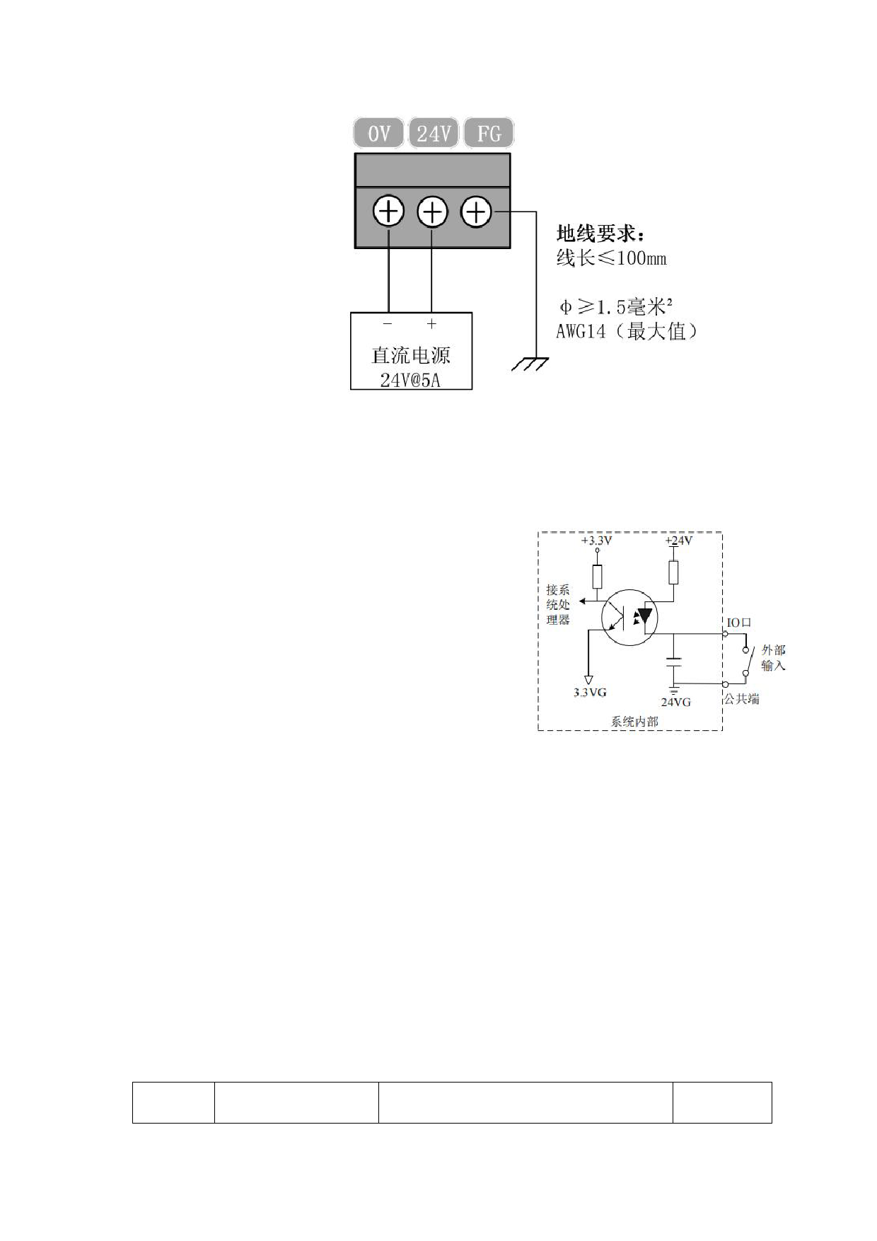
The input port is photoelectric isolated input
with low efficiency. The input signal can be
mechanical contact switch, or photoelectric
switch, support often open and closed input.
The common end of the external switch is 24 VGND,
and the other end is connected to the
corresponding input port. The schematic
diagram of the input port internal circuit is shown in Figure 14.3.
A total of 16 input ports.
The input signal pin definition can be modified.
Input signals are defined by default as described in Table 1 4.2.
Figure 14.3 Schematic diagram of the input interface circuit
There are 16 universal input ports, and all input port functions support
customization. Each axis of the limit, zero and emergency stop functions, support serial
number customization.
Table 1 4.2 Input port definitions
order
number
function
explain
remarks
136
 RAYCUT-Lite L5210H CNC Laser Cutting Controller Manual")
 RAYCUT-Lite L5210H CNC Laser Cutting Controller Manual")
 RAYCUT-Lite L5210H CNC Laser Cutting Controller Manual")
 RAYCUT-Lite L5210H CNC Laser Cutting Controller Manual")
 RAYCUT-Lite L5210H CNC Laser Cutting Controller Manual")
 RAYCUT-Lite L5210H CNC Laser Cutting Controller Manual")
 RAYCUT-Lite L5210H CNC Laser Cutting Controller Manual")
 RAYCUT-Lite L5210H CNC Laser Cutting Controller Manual")
 RAYCUT-Lite L5210H CNC Laser Cutting Controller Manual")
 RAYCUT-Lite L5210H CNC Laser Cutting Controller Manual")
 RAYCUT-Lite L5210H CNC Laser Cutting Controller Manual")
 RAYCUT-Lite L5210H CNC Laser Cutting Controller Manual")
 RAYCUT-Lite L5210H CNC Laser Cutting Controller Manual")
 RAYCUT-Lite L5210H CNC Laser Cutting Controller Manual")
 RAYCUT-Lite L5210H CNC Laser Cutting Controller Manual")
 RAYCUT-Lite L5210H CNC Laser Cutting Controller Manual")
 RAYCUT-Lite L5210H CNC Laser Cutting Controller Manual")
 RAYCUT-Lite L5210H CNC Laser Cutting Controller Manual")
 RAYCUT-Lite L5210H CNC Laser Cutting Controller Manual")
 RAYCUT-Lite L5210H CNC Laser Cutting Controller Manual")
 RAYCUT-Lite L5210H CNC Laser Cutting Controller Manual")
 RAYCUT-Lite L5210H CNC Laser Cutting Controller Manual")
 RAYCUT-Lite L5210H CNC Laser Cutting Controller Manual")
 RAYCUT-Lite L5210H CNC Laser Cutting Controller Manual")
 RAYCUT-Lite L5210H CNC Laser Cutting Controller Manual")
 RAYCUT-Lite L5210H CNC Laser Cutting Controller Manual")
 RAYCUT-Lite L5210H CNC Laser Cutting Controller Manual")
 RAYCUT-Lite L5210H CNC Laser Cutting Controller Manual")
 RAYCUT-Lite L5210H CNC Laser Cutting Controller Manual")
 RAYCUT-Lite L5210H CNC Laser Cutting Controller Manual")
 RAYCUT-Lite L5210H CNC Laser Cutting Controller Manual")
 RAYCUT-Lite L5210H CNC Laser Cutting Controller Manual")
 RAYCUT-Lite L5210H CNC Laser Cutting Controller Manual")
 RAYCUT-Lite L5210H CNC Laser Cutting Controller Manual")
 RAYCUT-Lite L5210H CNC Laser Cutting Controller Manual")
 RAYCUT-Lite L5210H CNC Laser Cutting Controller Manual")
 RAYCUT-Lite L5210H CNC Laser Cutting Controller Manual")
 RAYCUT-Lite L5210H CNC Laser Cutting Controller Manual")
 RAYCUT-Lite L5210H CNC Laser Cutting Controller Manual")
 RAYCUT-Lite L5210H CNC Laser Cutting Controller Manual")
 RAYCUT-Lite L5210H CNC Laser Cutting Controller Manual")
 RAYCUT-Lite L5210H CNC Laser Cutting Controller Manual")
 RAYCUT-Lite L5210H CNC Laser Cutting Controller Manual")
 RAYCUT-Lite L5210H CNC Laser Cutting Controller Manual")
 RAYCUT-Lite L5210H CNC Laser Cutting Controller Manual")
 RAYCUT-Lite L5210H CNC Laser Cutting Controller Manual")
 RAYCUT-Lite L5210H CNC Laser Cutting Controller Manual")
 RAYCUT-Lite L5210H CNC Laser Cutting Controller Manual")
 RAYCUT-Lite L5210H CNC Laser Cutting Controller Manual")
 RAYCUT-Lite L5210H CNC Laser Cutting Controller Manual")
 RAYCUT-Lite L5210H CNC Laser Cutting Controller Manual")
 RAYCUT-Lite L5210H CNC Laser Cutting Controller Manual")
 RAYCUT-Lite L5210H CNC Laser Cutting Controller Manual")
 RAYCUT-Lite L5210H CNC Laser Cutting Controller Manual")
 RAYCUT-Lite L5210H CNC Laser Cutting Controller Manual")
 RAYCUT-Lite L5210H CNC Laser Cutting Controller Manual")
 RAYCUT-Lite L5210H CNC Laser Cutting Controller Manual")
 RAYCUT-Lite L5210H CNC Laser Cutting Controller Manual")
 RAYCUT-Lite L5210H CNC Laser Cutting Controller Manual")
 RAYCUT-Lite L5210H CNC Laser Cutting Controller Manual")
 RAYCUT-Lite L5210H CNC Laser Cutting Controller Manual")
 RAYCUT-Lite L5210H CNC Laser Cutting Controller Manual")
 RAYCUT-Lite L5210H CNC Laser Cutting Controller Manual")
 RAYCUT-Lite L5210H CNC Laser Cutting Controller Manual")
 RAYCUT-Lite L5210H CNC Laser Cutting Controller Manual")
 RAYCUT-Lite L5210H CNC Laser Cutting Controller Manual")
 RAYCUT-Lite L5210H CNC Laser Cutting Controller Manual")
 RAYCUT-Lite L5210H CNC Laser Cutting Controller Manual")
 RAYCUT-Lite L5210H CNC Laser Cutting Controller Manual")
 RAYCUT-Lite L5210H CNC Laser Cutting Controller Manual")
 RAYCUT-Lite L5210H CNC Laser Cutting Controller Manual")
 RAYCUT-Lite L5210H CNC Laser Cutting Controller Manual")
 RAYCUT-Lite L5210H CNC Laser Cutting Controller Manual")
 RAYCUT-Lite L5210H CNC Laser Cutting Controller Manual")
 RAYCUT-Lite L5210H CNC Laser Cutting Controller Manual")
 RAYCUT-Lite L5210H CNC Laser Cutting Controller Manual")
 RAYCUT-Lite L5210H CNC Laser Cutting Controller Manual")
 RAYCUT-Lite L5210H CNC Laser Cutting Controller Manual")
 RAYCUT-Lite L5210H CNC Laser Cutting Controller Manual")
 RAYCUT-Lite L5210H CNC Laser Cutting Controller Manual")
 RAYCUT-Lite L5210H CNC Laser Cutting Controller Manual")
 RAYCUT-Lite L5210H CNC Laser Cutting Controller Manual")
 RAYCUT-Lite L5210H CNC Laser Cutting Controller Manual")
 RAYCUT-Lite L5210H CNC Laser Cutting Controller Manual")
 RAYCUT-Lite L5210H CNC Laser Cutting Controller Manual")
 RAYCUT-Lite L5210H CNC Laser Cutting Controller Manual")
 RAYCUT-Lite L5210H CNC Laser Cutting Controller Manual")
 RAYCUT-Lite L5210H CNC Laser Cutting Controller Manual")
 RAYCUT-Lite L5210H CNC Laser Cutting Controller Manual")
 RAYCUT-Lite L5210H CNC Laser Cutting Controller Manual")
 RAYCUT-Lite L5210H CNC Laser Cutting Controller Manual")
 RAYCUT-Lite L5210H CNC Laser Cutting Controller Manual")
 RAYCUT-Lite L5210H CNC Laser Cutting Controller Manual")
 RAYCUT-Lite L5210H CNC Laser Cutting Controller Manual")
 RAYCUT-Lite L5210H CNC Laser Cutting Controller Manual")
 RAYCUT-Lite L5210H CNC Laser Cutting Controller Manual")
 RAYCUT-Lite L5210H CNC Laser Cutting Controller Manual")
 RAYCUT-Lite L5210H CNC Laser Cutting Controller Manual")
 RAYCUT-Lite L5210H CNC Laser Cutting Controller Manual")
 RAYCUT-Lite L5210H CNC Laser Cutting Controller Manual")
 RAYCUT-Lite L5210H CNC Laser Cutting Controller Manual")
 RAYCUT-Lite L5210H CNC Laser Cutting Controller Manual")
 RAYCUT-Lite L5210H CNC Laser Cutting Controller Manual")
 RAYCUT-Lite L5210H CNC Laser Cutting Controller Manual")
 RAYCUT-Lite L5210H CNC Laser Cutting Controller Manual")
 RAYCUT-Lite L5210H CNC Laser Cutting Controller Manual")
 RAYCUT-Lite L5210H CNC Laser Cutting Controller Manual")
 RAYCUT-Lite L5210H CNC Laser Cutting Controller Manual")
 RAYCUT-Lite L5210H CNC Laser Cutting Controller Manual")
 RAYCUT-Lite L5210H CNC Laser Cutting Controller Manual")
 RAYCUT-Lite L5210H CNC Laser Cutting Controller Manual")
 RAYCUT-Lite L5210H CNC Laser Cutting Controller Manual")
 RAYCUT-Lite L5210H CNC Laser Cutting Controller Manual")
 RAYCUT-Lite L5210H CNC Laser Cutting Controller Manual")
 RAYCUT-Lite L5210H CNC Laser Cutting Controller Manual")
 RAYCUT-Lite L5210H CNC Laser Cutting Controller Manual")
 RAYCUT-Lite L5210H CNC Laser Cutting Controller Manual")
 RAYCUT-Lite L5210H CNC Laser Cutting Controller Manual")
 RAYCUT-Lite L5210H CNC Laser Cutting Controller Manual")
 RAYCUT-Lite L5210H CNC Laser Cutting Controller Manual")
 RAYCUT-Lite L5210H CNC Laser Cutting Controller Manual")
 RAYCUT-Lite L5210H CNC Laser Cutting Controller Manual")
 RAYCUT-Lite L5210H CNC Laser Cutting Controller Manual")
 RAYCUT-Lite L5210H CNC Laser Cutting Controller Manual")
 RAYCUT-Lite L5210H CNC Laser Cutting Controller Manual")
 RAYCUT-Lite L5210H CNC Laser Cutting Controller Manual")
 RAYCUT-Lite L5210H CNC Laser Cutting Controller Manual")
 RAYCUT-Lite L5210H CNC Laser Cutting Controller Manual")
 RAYCUT-Lite L5210H CNC Laser Cutting Controller Manual")
 RAYCUT-Lite L5210H CNC Laser Cutting Controller Manual")
 RAYCUT-Lite L5210H CNC Laser Cutting Controller Manual")
 RAYCUT-Lite L5210H CNC Laser Cutting Controller Manual")
 RAYCUT-Lite L5210H CNC Laser Cutting Controller Manual")
 RAYCUT-Lite L5210H CNC Laser Cutting Controller Manual")

 RAYCUT-Lite L5210H CNC Laser Cutting Controller Manual")