
Chapter 12 graphic management
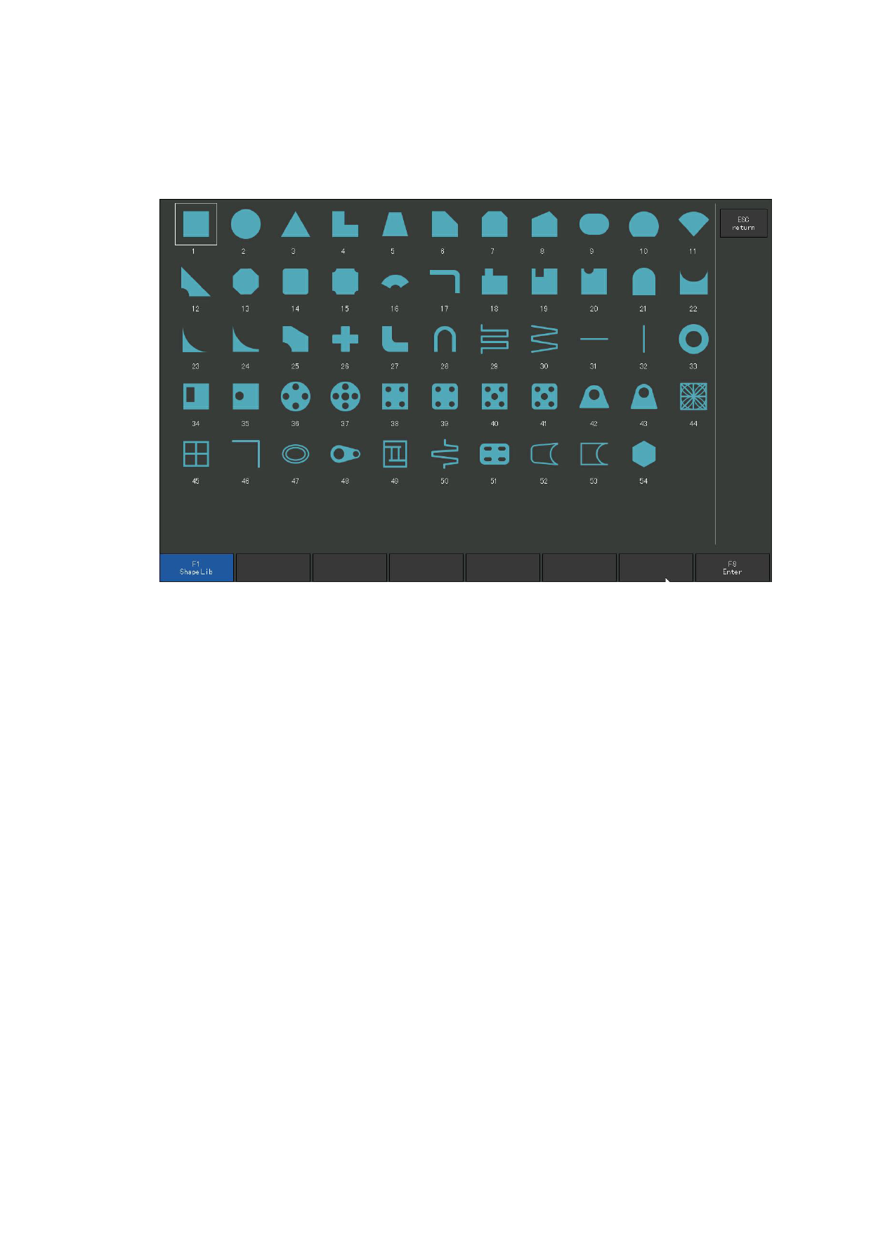
Under the main interface, press [F1] to enter the shapelib page, as shown
in Figure 12.1.
Figure 12.1, the gallery page
On this screen, press [↑], [↓], [←], and [→] to select different drawings.
12.1 Select the graphics / piece size
In plate cutting mode, after moving the cursor to the desired figure on the gallery
homepage interface, press [F8] to confirm and select a gallery, as shown in Figure 12.2.
For the first use, the piece size interface is displayed (the piece size refers to the
cut workpiece is needed, and the hole size refers to the cut hole is needed). In later
use, the previous parameter setting (piece size or hole size) will be maintained. The
bottom right of the screen shows the schematic diagram of the current artifact. The
modifiable parameters are represented by numbers. In the schematic diagram, it can be
seen in the specific position, with length, Angle and other units. The left side of the
screen shows the actual renderings of the current artifact.
[↑], [↓], [←], [→] can select the dimensions to be modified. Use the number
key to modify the parameters, press [F8] to confirm, and then enter the drawing
On the cutting function interface in Figure 12.3, if there is a kerf setting,
the original outline line (green line) and the kerf line (blue line) will be displayed
at the same time. When cutting, the center of the torch is cut along the blue line.
110
 RAYCUT-Lite L5210H CNC Laser Cutting Controller Manual")
 RAYCUT-Lite L5210H CNC Laser Cutting Controller Manual")
 RAYCUT-Lite L5210H CNC Laser Cutting Controller Manual")
 RAYCUT-Lite L5210H CNC Laser Cutting Controller Manual")
 RAYCUT-Lite L5210H CNC Laser Cutting Controller Manual")
 RAYCUT-Lite L5210H CNC Laser Cutting Controller Manual")
 RAYCUT-Lite L5210H CNC Laser Cutting Controller Manual")
 RAYCUT-Lite L5210H CNC Laser Cutting Controller Manual")
 RAYCUT-Lite L5210H CNC Laser Cutting Controller Manual")
 RAYCUT-Lite L5210H CNC Laser Cutting Controller Manual")
 RAYCUT-Lite L5210H CNC Laser Cutting Controller Manual")
 RAYCUT-Lite L5210H CNC Laser Cutting Controller Manual")
 RAYCUT-Lite L5210H CNC Laser Cutting Controller Manual")
 RAYCUT-Lite L5210H CNC Laser Cutting Controller Manual")
 RAYCUT-Lite L5210H CNC Laser Cutting Controller Manual")
 RAYCUT-Lite L5210H CNC Laser Cutting Controller Manual")
 RAYCUT-Lite L5210H CNC Laser Cutting Controller Manual")
 RAYCUT-Lite L5210H CNC Laser Cutting Controller Manual")
 RAYCUT-Lite L5210H CNC Laser Cutting Controller Manual")
 RAYCUT-Lite L5210H CNC Laser Cutting Controller Manual")
 RAYCUT-Lite L5210H CNC Laser Cutting Controller Manual")
 RAYCUT-Lite L5210H CNC Laser Cutting Controller Manual")
 RAYCUT-Lite L5210H CNC Laser Cutting Controller Manual")
 RAYCUT-Lite L5210H CNC Laser Cutting Controller Manual")
 RAYCUT-Lite L5210H CNC Laser Cutting Controller Manual")
 RAYCUT-Lite L5210H CNC Laser Cutting Controller Manual")
 RAYCUT-Lite L5210H CNC Laser Cutting Controller Manual")
 RAYCUT-Lite L5210H CNC Laser Cutting Controller Manual")
 RAYCUT-Lite L5210H CNC Laser Cutting Controller Manual")
 RAYCUT-Lite L5210H CNC Laser Cutting Controller Manual")
 RAYCUT-Lite L5210H CNC Laser Cutting Controller Manual")
 RAYCUT-Lite L5210H CNC Laser Cutting Controller Manual")
 RAYCUT-Lite L5210H CNC Laser Cutting Controller Manual")
 RAYCUT-Lite L5210H CNC Laser Cutting Controller Manual")
 RAYCUT-Lite L5210H CNC Laser Cutting Controller Manual")
 RAYCUT-Lite L5210H CNC Laser Cutting Controller Manual")
 RAYCUT-Lite L5210H CNC Laser Cutting Controller Manual")
 RAYCUT-Lite L5210H CNC Laser Cutting Controller Manual")
 RAYCUT-Lite L5210H CNC Laser Cutting Controller Manual")
 RAYCUT-Lite L5210H CNC Laser Cutting Controller Manual")
 RAYCUT-Lite L5210H CNC Laser Cutting Controller Manual")
 RAYCUT-Lite L5210H CNC Laser Cutting Controller Manual")
 RAYCUT-Lite L5210H CNC Laser Cutting Controller Manual")
 RAYCUT-Lite L5210H CNC Laser Cutting Controller Manual")
 RAYCUT-Lite L5210H CNC Laser Cutting Controller Manual")
 RAYCUT-Lite L5210H CNC Laser Cutting Controller Manual")
 RAYCUT-Lite L5210H CNC Laser Cutting Controller Manual")
 RAYCUT-Lite L5210H CNC Laser Cutting Controller Manual")
 RAYCUT-Lite L5210H CNC Laser Cutting Controller Manual")
 RAYCUT-Lite L5210H CNC Laser Cutting Controller Manual")
 RAYCUT-Lite L5210H CNC Laser Cutting Controller Manual")
 RAYCUT-Lite L5210H CNC Laser Cutting Controller Manual")
 RAYCUT-Lite L5210H CNC Laser Cutting Controller Manual")
 RAYCUT-Lite L5210H CNC Laser Cutting Controller Manual")
 RAYCUT-Lite L5210H CNC Laser Cutting Controller Manual")
 RAYCUT-Lite L5210H CNC Laser Cutting Controller Manual")
 RAYCUT-Lite L5210H CNC Laser Cutting Controller Manual")
 RAYCUT-Lite L5210H CNC Laser Cutting Controller Manual")
 RAYCUT-Lite L5210H CNC Laser Cutting Controller Manual")
 RAYCUT-Lite L5210H CNC Laser Cutting Controller Manual")
 RAYCUT-Lite L5210H CNC Laser Cutting Controller Manual")
 RAYCUT-Lite L5210H CNC Laser Cutting Controller Manual")
 RAYCUT-Lite L5210H CNC Laser Cutting Controller Manual")
 RAYCUT-Lite L5210H CNC Laser Cutting Controller Manual")
 RAYCUT-Lite L5210H CNC Laser Cutting Controller Manual")
 RAYCUT-Lite L5210H CNC Laser Cutting Controller Manual")
 RAYCUT-Lite L5210H CNC Laser Cutting Controller Manual")
 RAYCUT-Lite L5210H CNC Laser Cutting Controller Manual")
 RAYCUT-Lite L5210H CNC Laser Cutting Controller Manual")
 RAYCUT-Lite L5210H CNC Laser Cutting Controller Manual")
 RAYCUT-Lite L5210H CNC Laser Cutting Controller Manual")
 RAYCUT-Lite L5210H CNC Laser Cutting Controller Manual")
 RAYCUT-Lite L5210H CNC Laser Cutting Controller Manual")
 RAYCUT-Lite L5210H CNC Laser Cutting Controller Manual")
 RAYCUT-Lite L5210H CNC Laser Cutting Controller Manual")
 RAYCUT-Lite L5210H CNC Laser Cutting Controller Manual")
 RAYCUT-Lite L5210H CNC Laser Cutting Controller Manual")
 RAYCUT-Lite L5210H CNC Laser Cutting Controller Manual")
 RAYCUT-Lite L5210H CNC Laser Cutting Controller Manual")
 RAYCUT-Lite L5210H CNC Laser Cutting Controller Manual")
 RAYCUT-Lite L5210H CNC Laser Cutting Controller Manual")
 RAYCUT-Lite L5210H CNC Laser Cutting Controller Manual")
 RAYCUT-Lite L5210H CNC Laser Cutting Controller Manual")
 RAYCUT-Lite L5210H CNC Laser Cutting Controller Manual")
 RAYCUT-Lite L5210H CNC Laser Cutting Controller Manual")
 RAYCUT-Lite L5210H CNC Laser Cutting Controller Manual")
 RAYCUT-Lite L5210H CNC Laser Cutting Controller Manual")
 RAYCUT-Lite L5210H CNC Laser Cutting Controller Manual")
 RAYCUT-Lite L5210H CNC Laser Cutting Controller Manual")
 RAYCUT-Lite L5210H CNC Laser Cutting Controller Manual")
 RAYCUT-Lite L5210H CNC Laser Cutting Controller Manual")
 RAYCUT-Lite L5210H CNC Laser Cutting Controller Manual")
 RAYCUT-Lite L5210H CNC Laser Cutting Controller Manual")
 RAYCUT-Lite L5210H CNC Laser Cutting Controller Manual")
 RAYCUT-Lite L5210H CNC Laser Cutting Controller Manual")
 RAYCUT-Lite L5210H CNC Laser Cutting Controller Manual")
 RAYCUT-Lite L5210H CNC Laser Cutting Controller Manual")
 RAYCUT-Lite L5210H CNC Laser Cutting Controller Manual")
 RAYCUT-Lite L5210H CNC Laser Cutting Controller Manual")
 RAYCUT-Lite L5210H CNC Laser Cutting Controller Manual")
 RAYCUT-Lite L5210H CNC Laser Cutting Controller Manual")
 RAYCUT-Lite L5210H CNC Laser Cutting Controller Manual")
 RAYCUT-Lite L5210H CNC Laser Cutting Controller Manual")
 RAYCUT-Lite L5210H CNC Laser Cutting Controller Manual")
 RAYCUT-Lite L5210H CNC Laser Cutting Controller Manual")
 RAYCUT-Lite L5210H CNC Laser Cutting Controller Manual")
 RAYCUT-Lite L5210H CNC Laser Cutting Controller Manual")
 RAYCUT-Lite L5210H CNC Laser Cutting Controller Manual")
 RAYCUT-Lite L5210H CNC Laser Cutting Controller Manual")
 RAYCUT-Lite L5210H CNC Laser Cutting Controller Manual")
 RAYCUT-Lite L5210H CNC Laser Cutting Controller Manual")
 RAYCUT-Lite L5210H CNC Laser Cutting Controller Manual")
 RAYCUT-Lite L5210H CNC Laser Cutting Controller Manual")
 RAYCUT-Lite L5210H CNC Laser Cutting Controller Manual")
 RAYCUT-Lite L5210H CNC Laser Cutting Controller Manual")
 RAYCUT-Lite L5210H CNC Laser Cutting Controller Manual")
 RAYCUT-Lite L5210H CNC Laser Cutting Controller Manual")
 RAYCUT-Lite L5210H CNC Laser Cutting Controller Manual")
 RAYCUT-Lite L5210H CNC Laser Cutting Controller Manual")
 RAYCUT-Lite L5210H CNC Laser Cutting Controller Manual")
 RAYCUT-Lite L5210H CNC Laser Cutting Controller Manual")
 RAYCUT-Lite L5210H CNC Laser Cutting Controller Manual")
 RAYCUT-Lite L5210H CNC Laser Cutting Controller Manual")
 RAYCUT-Lite L5210H CNC Laser Cutting Controller Manual")
 RAYCUT-Lite L5210H CNC Laser Cutting Controller Manual")
 RAYCUT-Lite L5210H CNC Laser Cutting Controller Manual")
 RAYCUT-Lite L5210H CNC Laser Cutting Controller Manual")
 RAYCUT-Lite L5210H CNC Laser Cutting Controller Manual")
 RAYCUT-Lite L5210H CNC Laser Cutting Controller Manual")
 RAYCUT-Lite L5210H CNC Laser Cutting Controller Manual")
 RAYCUT-Lite L5210H CNC Laser Cutting Controller Manual")
 RAYCUT-Lite L5210H CNC Laser Cutting Controller Manual")
 RAYCUT-Lite L5210H CNC Laser Cutting Controller Manual")
 RAYCUT-Lite L5210H CNC Laser Cutting Controller Manual")

 RAYCUT-Lite L5210H CNC Laser Cutting Controller Manual")