
M08
M02
M07
The
spacing
follows
the dock
optical shutter)
(effective output
foll
ow
Set the
focus
PWM / laser
DA PWM +
enables
PWM-enable
s
Start positioning the cut and lifting it back
Gas valve /
Until stay G01, G02, G03 (system stop
total valve
Cut Time-delay judgment
nozz
le
heig
ht
(hol
d
le
Whetheranto reach the position
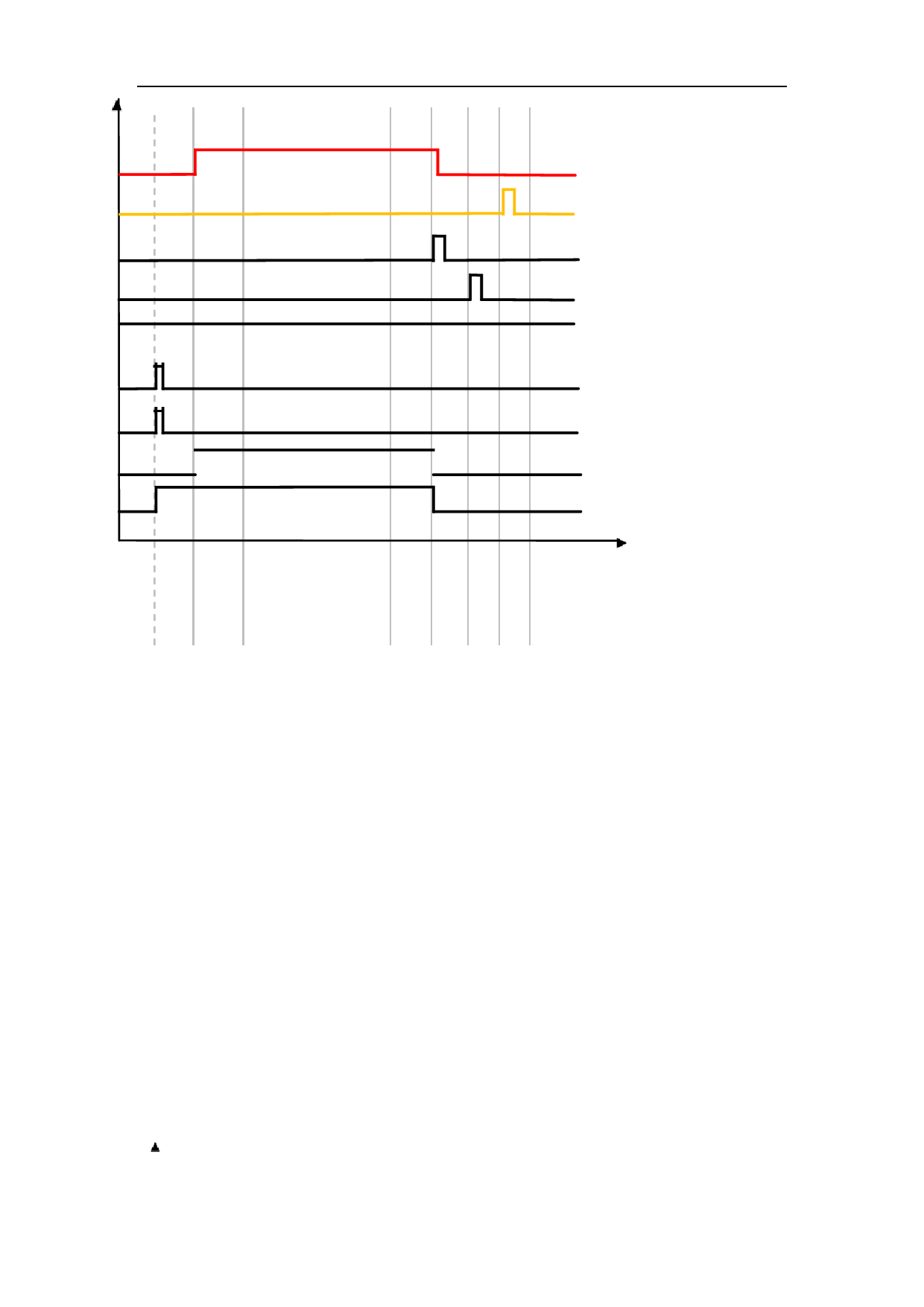
pour:
1) The Y-axis black line segment represents the system output command;
2) Other colors represent the system input command;
3) Spacing following: refers to the cutting gun to always keep a certain distance from the plate,
that is, the following state;
4) Follow in place: the system controls the elevation regulator to reach a certain position,
not necessarily keeping the following state. Lift up, dock back, and follow instructions
all require feedback signals.
A2.2 Time diagram of laser three-stage perforation process
Time iming diagram of laser tertiary perforation process
(Secondary
progressive
144
 RAYCUT-Lite L5210H CNC Laser Cutting Controller Manual")
 RAYCUT-Lite L5210H CNC Laser Cutting Controller Manual")
 RAYCUT-Lite L5210H CNC Laser Cutting Controller Manual")
 RAYCUT-Lite L5210H CNC Laser Cutting Controller Manual")
 RAYCUT-Lite L5210H CNC Laser Cutting Controller Manual")
 RAYCUT-Lite L5210H CNC Laser Cutting Controller Manual")
 RAYCUT-Lite L5210H CNC Laser Cutting Controller Manual")
 RAYCUT-Lite L5210H CNC Laser Cutting Controller Manual")
 RAYCUT-Lite L5210H CNC Laser Cutting Controller Manual")
 RAYCUT-Lite L5210H CNC Laser Cutting Controller Manual")
 RAYCUT-Lite L5210H CNC Laser Cutting Controller Manual")
 RAYCUT-Lite L5210H CNC Laser Cutting Controller Manual")
 RAYCUT-Lite L5210H CNC Laser Cutting Controller Manual")
 RAYCUT-Lite L5210H CNC Laser Cutting Controller Manual")
 RAYCUT-Lite L5210H CNC Laser Cutting Controller Manual")
 RAYCUT-Lite L5210H CNC Laser Cutting Controller Manual")
 RAYCUT-Lite L5210H CNC Laser Cutting Controller Manual")
 RAYCUT-Lite L5210H CNC Laser Cutting Controller Manual")
 RAYCUT-Lite L5210H CNC Laser Cutting Controller Manual")
 RAYCUT-Lite L5210H CNC Laser Cutting Controller Manual")
 RAYCUT-Lite L5210H CNC Laser Cutting Controller Manual")
 RAYCUT-Lite L5210H CNC Laser Cutting Controller Manual")
 RAYCUT-Lite L5210H CNC Laser Cutting Controller Manual")
 RAYCUT-Lite L5210H CNC Laser Cutting Controller Manual")
 RAYCUT-Lite L5210H CNC Laser Cutting Controller Manual")
 RAYCUT-Lite L5210H CNC Laser Cutting Controller Manual")
 RAYCUT-Lite L5210H CNC Laser Cutting Controller Manual")
 RAYCUT-Lite L5210H CNC Laser Cutting Controller Manual")
 RAYCUT-Lite L5210H CNC Laser Cutting Controller Manual")
 RAYCUT-Lite L5210H CNC Laser Cutting Controller Manual")
 RAYCUT-Lite L5210H CNC Laser Cutting Controller Manual")
 RAYCUT-Lite L5210H CNC Laser Cutting Controller Manual")
 RAYCUT-Lite L5210H CNC Laser Cutting Controller Manual")
 RAYCUT-Lite L5210H CNC Laser Cutting Controller Manual")
 RAYCUT-Lite L5210H CNC Laser Cutting Controller Manual")
 RAYCUT-Lite L5210H CNC Laser Cutting Controller Manual")
 RAYCUT-Lite L5210H CNC Laser Cutting Controller Manual")
 RAYCUT-Lite L5210H CNC Laser Cutting Controller Manual")
 RAYCUT-Lite L5210H CNC Laser Cutting Controller Manual")
 RAYCUT-Lite L5210H CNC Laser Cutting Controller Manual")
 RAYCUT-Lite L5210H CNC Laser Cutting Controller Manual")
 RAYCUT-Lite L5210H CNC Laser Cutting Controller Manual")
 RAYCUT-Lite L5210H CNC Laser Cutting Controller Manual")
 RAYCUT-Lite L5210H CNC Laser Cutting Controller Manual")
 RAYCUT-Lite L5210H CNC Laser Cutting Controller Manual")
 RAYCUT-Lite L5210H CNC Laser Cutting Controller Manual")
 RAYCUT-Lite L5210H CNC Laser Cutting Controller Manual")
 RAYCUT-Lite L5210H CNC Laser Cutting Controller Manual")
 RAYCUT-Lite L5210H CNC Laser Cutting Controller Manual")
 RAYCUT-Lite L5210H CNC Laser Cutting Controller Manual")
 RAYCUT-Lite L5210H CNC Laser Cutting Controller Manual")
 RAYCUT-Lite L5210H CNC Laser Cutting Controller Manual")
 RAYCUT-Lite L5210H CNC Laser Cutting Controller Manual")
 RAYCUT-Lite L5210H CNC Laser Cutting Controller Manual")
 RAYCUT-Lite L5210H CNC Laser Cutting Controller Manual")
 RAYCUT-Lite L5210H CNC Laser Cutting Controller Manual")
 RAYCUT-Lite L5210H CNC Laser Cutting Controller Manual")
 RAYCUT-Lite L5210H CNC Laser Cutting Controller Manual")
 RAYCUT-Lite L5210H CNC Laser Cutting Controller Manual")
 RAYCUT-Lite L5210H CNC Laser Cutting Controller Manual")
 RAYCUT-Lite L5210H CNC Laser Cutting Controller Manual")
 RAYCUT-Lite L5210H CNC Laser Cutting Controller Manual")
 RAYCUT-Lite L5210H CNC Laser Cutting Controller Manual")
 RAYCUT-Lite L5210H CNC Laser Cutting Controller Manual")
 RAYCUT-Lite L5210H CNC Laser Cutting Controller Manual")
 RAYCUT-Lite L5210H CNC Laser Cutting Controller Manual")
 RAYCUT-Lite L5210H CNC Laser Cutting Controller Manual")
 RAYCUT-Lite L5210H CNC Laser Cutting Controller Manual")
 RAYCUT-Lite L5210H CNC Laser Cutting Controller Manual")
 RAYCUT-Lite L5210H CNC Laser Cutting Controller Manual")
 RAYCUT-Lite L5210H CNC Laser Cutting Controller Manual")
 RAYCUT-Lite L5210H CNC Laser Cutting Controller Manual")
 RAYCUT-Lite L5210H CNC Laser Cutting Controller Manual")
 RAYCUT-Lite L5210H CNC Laser Cutting Controller Manual")
 RAYCUT-Lite L5210H CNC Laser Cutting Controller Manual")
 RAYCUT-Lite L5210H CNC Laser Cutting Controller Manual")
 RAYCUT-Lite L5210H CNC Laser Cutting Controller Manual")
 RAYCUT-Lite L5210H CNC Laser Cutting Controller Manual")
 RAYCUT-Lite L5210H CNC Laser Cutting Controller Manual")
 RAYCUT-Lite L5210H CNC Laser Cutting Controller Manual")
 RAYCUT-Lite L5210H CNC Laser Cutting Controller Manual")
 RAYCUT-Lite L5210H CNC Laser Cutting Controller Manual")
 RAYCUT-Lite L5210H CNC Laser Cutting Controller Manual")
 RAYCUT-Lite L5210H CNC Laser Cutting Controller Manual")
 RAYCUT-Lite L5210H CNC Laser Cutting Controller Manual")
 RAYCUT-Lite L5210H CNC Laser Cutting Controller Manual")
 RAYCUT-Lite L5210H CNC Laser Cutting Controller Manual")
 RAYCUT-Lite L5210H CNC Laser Cutting Controller Manual")
 RAYCUT-Lite L5210H CNC Laser Cutting Controller Manual")
 RAYCUT-Lite L5210H CNC Laser Cutting Controller Manual")
 RAYCUT-Lite L5210H CNC Laser Cutting Controller Manual")
 RAYCUT-Lite L5210H CNC Laser Cutting Controller Manual")
 RAYCUT-Lite L5210H CNC Laser Cutting Controller Manual")
 RAYCUT-Lite L5210H CNC Laser Cutting Controller Manual")
 RAYCUT-Lite L5210H CNC Laser Cutting Controller Manual")
 RAYCUT-Lite L5210H CNC Laser Cutting Controller Manual")
 RAYCUT-Lite L5210H CNC Laser Cutting Controller Manual")
 RAYCUT-Lite L5210H CNC Laser Cutting Controller Manual")
 RAYCUT-Lite L5210H CNC Laser Cutting Controller Manual")
 RAYCUT-Lite L5210H CNC Laser Cutting Controller Manual")
 RAYCUT-Lite L5210H CNC Laser Cutting Controller Manual")
 RAYCUT-Lite L5210H CNC Laser Cutting Controller Manual")
 RAYCUT-Lite L5210H CNC Laser Cutting Controller Manual")
 RAYCUT-Lite L5210H CNC Laser Cutting Controller Manual")
 RAYCUT-Lite L5210H CNC Laser Cutting Controller Manual")
 RAYCUT-Lite L5210H CNC Laser Cutting Controller Manual")
 RAYCUT-Lite L5210H CNC Laser Cutting Controller Manual")
 RAYCUT-Lite L5210H CNC Laser Cutting Controller Manual")
 RAYCUT-Lite L5210H CNC Laser Cutting Controller Manual")
 RAYCUT-Lite L5210H CNC Laser Cutting Controller Manual")
 RAYCUT-Lite L5210H CNC Laser Cutting Controller Manual")
 RAYCUT-Lite L5210H CNC Laser Cutting Controller Manual")
 RAYCUT-Lite L5210H CNC Laser Cutting Controller Manual")
 RAYCUT-Lite L5210H CNC Laser Cutting Controller Manual")
 RAYCUT-Lite L5210H CNC Laser Cutting Controller Manual")
 RAYCUT-Lite L5210H CNC Laser Cutting Controller Manual")
 RAYCUT-Lite L5210H CNC Laser Cutting Controller Manual")
 RAYCUT-Lite L5210H CNC Laser Cutting Controller Manual")
 RAYCUT-Lite L5210H CNC Laser Cutting Controller Manual")
 RAYCUT-Lite L5210H CNC Laser Cutting Controller Manual")
 RAYCUT-Lite L5210H CNC Laser Cutting Controller Manual")
 RAYCUT-Lite L5210H CNC Laser Cutting Controller Manual")
 RAYCUT-Lite L5210H CNC Laser Cutting Controller Manual")
 RAYCUT-Lite L5210H CNC Laser Cutting Controller Manual")
 RAYCUT-Lite L5210H CNC Laser Cutting Controller Manual")
 RAYCUT-Lite L5210H CNC Laser Cutting Controller Manual")
 RAYCUT-Lite L5210H CNC Laser Cutting Controller Manual")
 RAYCUT-Lite L5210H CNC Laser Cutting Controller Manual")
 RAYCUT-Lite L5210H CNC Laser Cutting Controller Manual")
 RAYCUT-Lite L5210H CNC Laser Cutting Controller Manual")
 RAYCUT-Lite L5210H CNC Laser Cutting Controller Manual")
 RAYCUT-Lite L5210H CNC Laser Cutting Controller Manual")
 RAYCUT-Lite L5210H CNC Laser Cutting Controller Manual")
 RAYCUT-Lite L5210H CNC Laser Cutting Controller Manual")

 RAYCUT-Lite L5210H CNC Laser Cutting Controller Manual")