
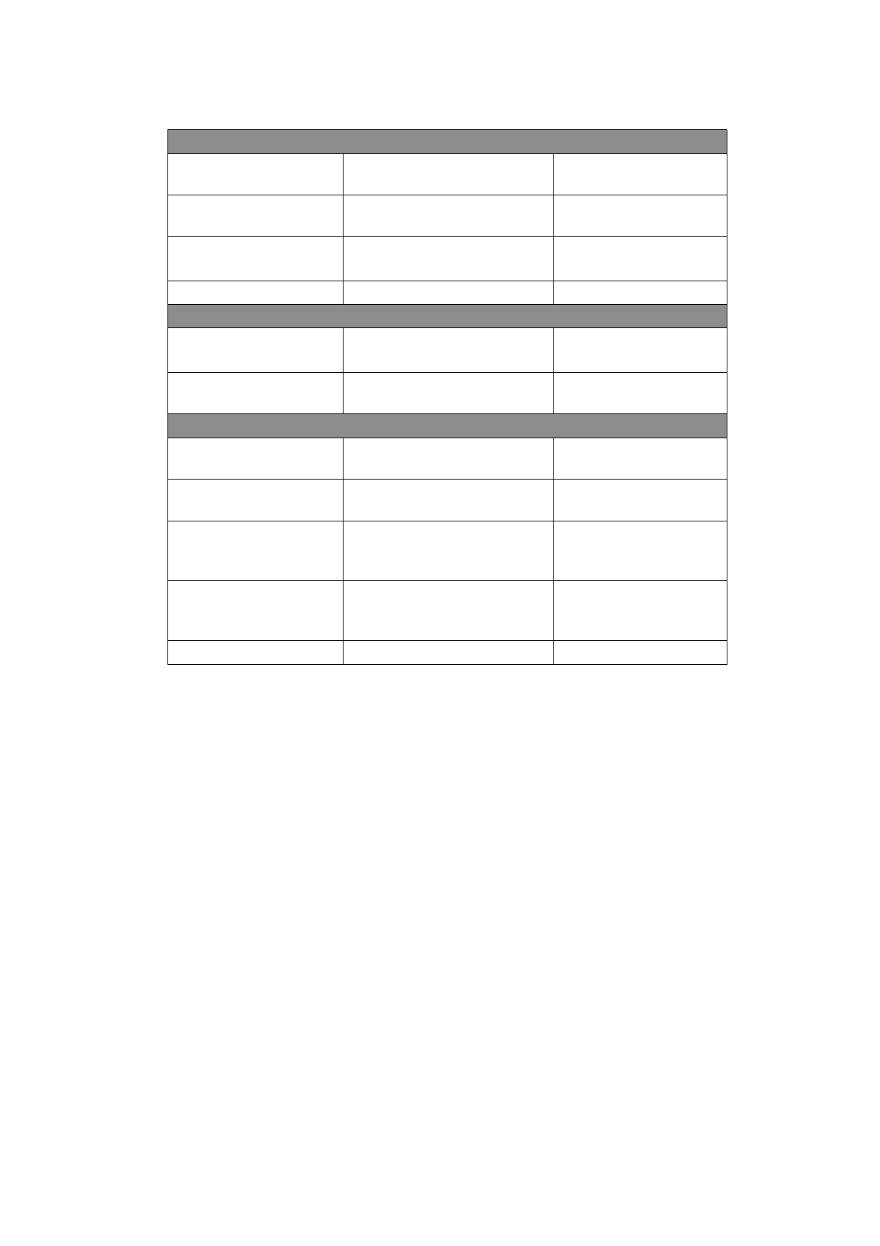
Table 1 3.2 Commonly used G, code table
G99
G92
G91 / G90
G20 / G21
Parameters: X / UY / VIJ
parameter:XY
No parameters
No parameters
Part option
parameters
Reference Point
Settings
Relative / absolute
coordinates
British / metric
G41 / G42
G40
No parameters
No parameters
Left / right kerf
compensation
Cancel kerf
compensation
G00
Parameters: X / UY / V Fast straight movement
(empty)
G01
Parameters: X / UY / V
Straight
cutting
G02
Parameters: X / UY / VIJ clockwise,
circular arc
cutting
G03
Parameters: X / UY / VIJ Counterclockwise
circular arc
cutting
G04
parameter:P
delay
1. G92 reference point setting
form:
G92[Xn][Yn]
Parameter meaning:
[Xn] [Yn] represents the absolute coordinates of the set reference point, and is also
the absolute coordinates of the machine tool back. If there is no parameter after G92, the
default reference point coordinate is (0,0). Generally, machine tools in (0,0) as the
reference point, this code can be omitted.
Note:
After the code is transferred, the reference point coordinates set by G92 will
be automatically saved. Before the new cut code, the reference point coordinate will
be valid, whether power off or not. After a new cut code is added, if the new code has
G92 instruction, the new reference point coordinate is the content after G92. If there
is no G92, the reference point is by default (0,0). A G92 can only appear once in a
code file.
example:
a.G92 X0 Y0
 RAYCUT-Lite L5210H CNC Laser Cutting Controller Manual")
 RAYCUT-Lite L5210H CNC Laser Cutting Controller Manual")
 RAYCUT-Lite L5210H CNC Laser Cutting Controller Manual")
 RAYCUT-Lite L5210H CNC Laser Cutting Controller Manual")
 RAYCUT-Lite L5210H CNC Laser Cutting Controller Manual")
 RAYCUT-Lite L5210H CNC Laser Cutting Controller Manual")
 RAYCUT-Lite L5210H CNC Laser Cutting Controller Manual")
 RAYCUT-Lite L5210H CNC Laser Cutting Controller Manual")
 RAYCUT-Lite L5210H CNC Laser Cutting Controller Manual")
 RAYCUT-Lite L5210H CNC Laser Cutting Controller Manual")
 RAYCUT-Lite L5210H CNC Laser Cutting Controller Manual")
 RAYCUT-Lite L5210H CNC Laser Cutting Controller Manual")
 RAYCUT-Lite L5210H CNC Laser Cutting Controller Manual")
 RAYCUT-Lite L5210H CNC Laser Cutting Controller Manual")
 RAYCUT-Lite L5210H CNC Laser Cutting Controller Manual")
 RAYCUT-Lite L5210H CNC Laser Cutting Controller Manual")
 RAYCUT-Lite L5210H CNC Laser Cutting Controller Manual")
 RAYCUT-Lite L5210H CNC Laser Cutting Controller Manual")
 RAYCUT-Lite L5210H CNC Laser Cutting Controller Manual")
 RAYCUT-Lite L5210H CNC Laser Cutting Controller Manual")
 RAYCUT-Lite L5210H CNC Laser Cutting Controller Manual")
 RAYCUT-Lite L5210H CNC Laser Cutting Controller Manual")
 RAYCUT-Lite L5210H CNC Laser Cutting Controller Manual")
 RAYCUT-Lite L5210H CNC Laser Cutting Controller Manual")
 RAYCUT-Lite L5210H CNC Laser Cutting Controller Manual")
 RAYCUT-Lite L5210H CNC Laser Cutting Controller Manual")
 RAYCUT-Lite L5210H CNC Laser Cutting Controller Manual")
 RAYCUT-Lite L5210H CNC Laser Cutting Controller Manual")
 RAYCUT-Lite L5210H CNC Laser Cutting Controller Manual")
 RAYCUT-Lite L5210H CNC Laser Cutting Controller Manual")
 RAYCUT-Lite L5210H CNC Laser Cutting Controller Manual")
 RAYCUT-Lite L5210H CNC Laser Cutting Controller Manual")
 RAYCUT-Lite L5210H CNC Laser Cutting Controller Manual")
 RAYCUT-Lite L5210H CNC Laser Cutting Controller Manual")
 RAYCUT-Lite L5210H CNC Laser Cutting Controller Manual")
 RAYCUT-Lite L5210H CNC Laser Cutting Controller Manual")
 RAYCUT-Lite L5210H CNC Laser Cutting Controller Manual")
 RAYCUT-Lite L5210H CNC Laser Cutting Controller Manual")
 RAYCUT-Lite L5210H CNC Laser Cutting Controller Manual")
 RAYCUT-Lite L5210H CNC Laser Cutting Controller Manual")
 RAYCUT-Lite L5210H CNC Laser Cutting Controller Manual")
 RAYCUT-Lite L5210H CNC Laser Cutting Controller Manual")
 RAYCUT-Lite L5210H CNC Laser Cutting Controller Manual")
 RAYCUT-Lite L5210H CNC Laser Cutting Controller Manual")
 RAYCUT-Lite L5210H CNC Laser Cutting Controller Manual")
 RAYCUT-Lite L5210H CNC Laser Cutting Controller Manual")
 RAYCUT-Lite L5210H CNC Laser Cutting Controller Manual")
 RAYCUT-Lite L5210H CNC Laser Cutting Controller Manual")
 RAYCUT-Lite L5210H CNC Laser Cutting Controller Manual")
 RAYCUT-Lite L5210H CNC Laser Cutting Controller Manual")
 RAYCUT-Lite L5210H CNC Laser Cutting Controller Manual")
 RAYCUT-Lite L5210H CNC Laser Cutting Controller Manual")
 RAYCUT-Lite L5210H CNC Laser Cutting Controller Manual")
 RAYCUT-Lite L5210H CNC Laser Cutting Controller Manual")
 RAYCUT-Lite L5210H CNC Laser Cutting Controller Manual")
 RAYCUT-Lite L5210H CNC Laser Cutting Controller Manual")
 RAYCUT-Lite L5210H CNC Laser Cutting Controller Manual")
 RAYCUT-Lite L5210H CNC Laser Cutting Controller Manual")
 RAYCUT-Lite L5210H CNC Laser Cutting Controller Manual")
 RAYCUT-Lite L5210H CNC Laser Cutting Controller Manual")
 RAYCUT-Lite L5210H CNC Laser Cutting Controller Manual")
 RAYCUT-Lite L5210H CNC Laser Cutting Controller Manual")
 RAYCUT-Lite L5210H CNC Laser Cutting Controller Manual")
 RAYCUT-Lite L5210H CNC Laser Cutting Controller Manual")
 RAYCUT-Lite L5210H CNC Laser Cutting Controller Manual")
 RAYCUT-Lite L5210H CNC Laser Cutting Controller Manual")
 RAYCUT-Lite L5210H CNC Laser Cutting Controller Manual")
 RAYCUT-Lite L5210H CNC Laser Cutting Controller Manual")
 RAYCUT-Lite L5210H CNC Laser Cutting Controller Manual")
 RAYCUT-Lite L5210H CNC Laser Cutting Controller Manual")
 RAYCUT-Lite L5210H CNC Laser Cutting Controller Manual")
 RAYCUT-Lite L5210H CNC Laser Cutting Controller Manual")
 RAYCUT-Lite L5210H CNC Laser Cutting Controller Manual")
 RAYCUT-Lite L5210H CNC Laser Cutting Controller Manual")
 RAYCUT-Lite L5210H CNC Laser Cutting Controller Manual")
 RAYCUT-Lite L5210H CNC Laser Cutting Controller Manual")
 RAYCUT-Lite L5210H CNC Laser Cutting Controller Manual")
 RAYCUT-Lite L5210H CNC Laser Cutting Controller Manual")
 RAYCUT-Lite L5210H CNC Laser Cutting Controller Manual")
 RAYCUT-Lite L5210H CNC Laser Cutting Controller Manual")
 RAYCUT-Lite L5210H CNC Laser Cutting Controller Manual")
 RAYCUT-Lite L5210H CNC Laser Cutting Controller Manual")
 RAYCUT-Lite L5210H CNC Laser Cutting Controller Manual")
 RAYCUT-Lite L5210H CNC Laser Cutting Controller Manual")
 RAYCUT-Lite L5210H CNC Laser Cutting Controller Manual")
 RAYCUT-Lite L5210H CNC Laser Cutting Controller Manual")
 RAYCUT-Lite L5210H CNC Laser Cutting Controller Manual")
 RAYCUT-Lite L5210H CNC Laser Cutting Controller Manual")
 RAYCUT-Lite L5210H CNC Laser Cutting Controller Manual")
 RAYCUT-Lite L5210H CNC Laser Cutting Controller Manual")
 RAYCUT-Lite L5210H CNC Laser Cutting Controller Manual")
 RAYCUT-Lite L5210H CNC Laser Cutting Controller Manual")
 RAYCUT-Lite L5210H CNC Laser Cutting Controller Manual")
 RAYCUT-Lite L5210H CNC Laser Cutting Controller Manual")
 RAYCUT-Lite L5210H CNC Laser Cutting Controller Manual")
 RAYCUT-Lite L5210H CNC Laser Cutting Controller Manual")
 RAYCUT-Lite L5210H CNC Laser Cutting Controller Manual")
 RAYCUT-Lite L5210H CNC Laser Cutting Controller Manual")
 RAYCUT-Lite L5210H CNC Laser Cutting Controller Manual")
 RAYCUT-Lite L5210H CNC Laser Cutting Controller Manual")
 RAYCUT-Lite L5210H CNC Laser Cutting Controller Manual")
 RAYCUT-Lite L5210H CNC Laser Cutting Controller Manual")
 RAYCUT-Lite L5210H CNC Laser Cutting Controller Manual")
 RAYCUT-Lite L5210H CNC Laser Cutting Controller Manual")
 RAYCUT-Lite L5210H CNC Laser Cutting Controller Manual")
 RAYCUT-Lite L5210H CNC Laser Cutting Controller Manual")
 RAYCUT-Lite L5210H CNC Laser Cutting Controller Manual")
 RAYCUT-Lite L5210H CNC Laser Cutting Controller Manual")
 RAYCUT-Lite L5210H CNC Laser Cutting Controller Manual")
 RAYCUT-Lite L5210H CNC Laser Cutting Controller Manual")
 RAYCUT-Lite L5210H CNC Laser Cutting Controller Manual")
 RAYCUT-Lite L5210H CNC Laser Cutting Controller Manual")
 RAYCUT-Lite L5210H CNC Laser Cutting Controller Manual")
 RAYCUT-Lite L5210H CNC Laser Cutting Controller Manual")
 RAYCUT-Lite L5210H CNC Laser Cutting Controller Manual")
 RAYCUT-Lite L5210H CNC Laser Cutting Controller Manual")
 RAYCUT-Lite L5210H CNC Laser Cutting Controller Manual")
 RAYCUT-Lite L5210H CNC Laser Cutting Controller Manual")
 RAYCUT-Lite L5210H CNC Laser Cutting Controller Manual")
 RAYCUT-Lite L5210H CNC Laser Cutting Controller Manual")
 RAYCUT-Lite L5210H CNC Laser Cutting Controller Manual")
 RAYCUT-Lite L5210H CNC Laser Cutting Controller Manual")
 RAYCUT-Lite L5210H CNC Laser Cutting Controller Manual")
 RAYCUT-Lite L5210H CNC Laser Cutting Controller Manual")
 RAYCUT-Lite L5210H CNC Laser Cutting Controller Manual")
 RAYCUT-Lite L5210H CNC Laser Cutting Controller Manual")
 RAYCUT-Lite L5210H CNC Laser Cutting Controller Manual")
 RAYCUT-Lite L5210H CNC Laser Cutting Controller Manual")
 RAYCUT-Lite L5210H CNC Laser Cutting Controller Manual")
 RAYCUT-Lite L5210H CNC Laser Cutting Controller Manual")
 RAYCUT-Lite L5210H CNC Laser Cutting Controller Manual")
 RAYCUT-Lite L5210H CNC Laser Cutting Controller Manual")
 RAYCUT-Lite L5210H CNC Laser Cutting Controller Manual")
 RAYCUT-Lite L5210H CNC Laser Cutting Controller Manual")

 RAYCUT-Lite L5210H CNC Laser Cutting Controller Manual")