
- You are here:
- AM.CO.ZABuythisCNC Utilities Homepage
- EasyRoute-CNC-Router
- EasyRoute CNC Control Panel Manufacture Manual.pdf
- Page 22 of 114
Specialized Concentrated Focused
Running State
When the machine tool is implementing any action, the system enters into “Running” State.
Pause State
When the machine tool is running, if the key of “pause during machining” is pressed, the system
will enter into PAUSE state and wait for further instruction. At this time, pressing the “Start” key will
make the system enter into “Running” state, while pressing the “Stop/Cancel” key will make the system
stop.
LOCK State
Lock state is an internal state occurring at the time of soft limit operation.
3.2. Coordinate System
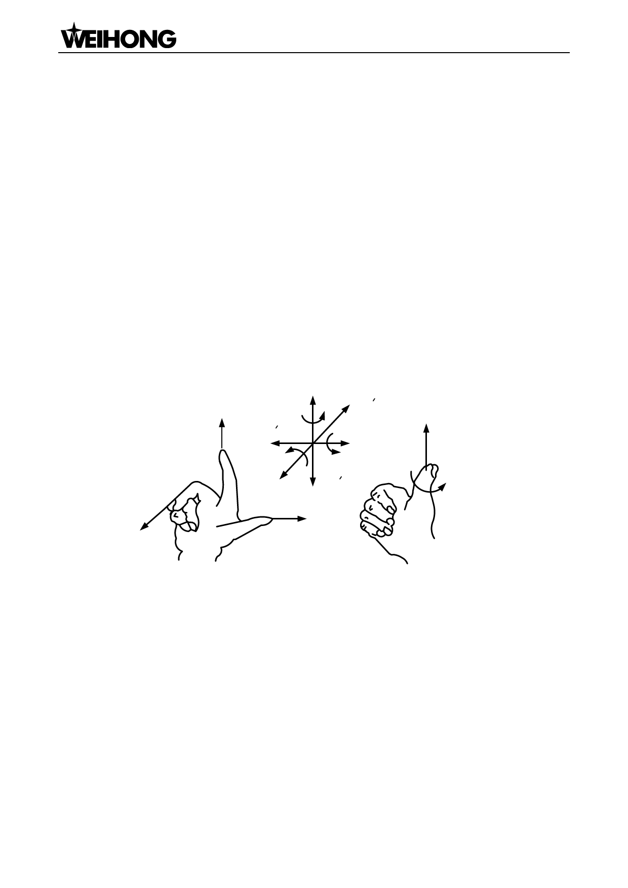
Coordinate system is a terminology that is used to describe the motion of a machine tool. For the
sake of unification, standard coordinate system adopts the right-hand rule. See Fig. 3-1.
+Y
+Z
+Y
+X
+C
+Z
+B +Z
+X
+A
+Y
+X
+X+Y+Z
+A+B
+C
Fig. 3-1 A coordinate system conforming to right-hand rule
For milling machines, the direction of machine axes is decided by both the type of machine tool
and the layout of each component. The basic coordinate axes of milling machines are X-axis, Y-axis,
and Z-axis:
——Z-axis is coincidental with spindle axis and the direction of the cutter moving away from
workpiece is its positive direction (+Z).
——X-axis is perpendicular to Z-axis and parallel to the clamped surface of workpiece. For the
single column vertical milling machine, if the user faces the spindle and looks in the column direction,
right moving direction is its positive direction (+ X).
——X-axis, Y-axis and Z-axis constitute a coordinate system adhering to the right-hand rule.
3.2.1. Machine Coordinate System
「10」Basic Concepts
 EasyRoute CNC Control Panel Manufacture Manual")
 EasyRoute CNC Control Panel Manufacture Manual")
 EasyRoute CNC Control Panel Manufacture Manual")
 EasyRoute CNC Control Panel Manufacture Manual")
 EasyRoute CNC Control Panel Manufacture Manual")
 EasyRoute CNC Control Panel Manufacture Manual")
 EasyRoute CNC Control Panel Manufacture Manual")
 EasyRoute CNC Control Panel Manufacture Manual")
 EasyRoute CNC Control Panel Manufacture Manual")
 EasyRoute CNC Control Panel Manufacture Manual")
 EasyRoute CNC Control Panel Manufacture Manual")
 EasyRoute CNC Control Panel Manufacture Manual")
 EasyRoute CNC Control Panel Manufacture Manual")
 EasyRoute CNC Control Panel Manufacture Manual")
 EasyRoute CNC Control Panel Manufacture Manual")
 EasyRoute CNC Control Panel Manufacture Manual")
 EasyRoute CNC Control Panel Manufacture Manual")
 EasyRoute CNC Control Panel Manufacture Manual")
 EasyRoute CNC Control Panel Manufacture Manual")
 EasyRoute CNC Control Panel Manufacture Manual")
 EasyRoute CNC Control Panel Manufacture Manual")
 EasyRoute CNC Control Panel Manufacture Manual")
 EasyRoute CNC Control Panel Manufacture Manual")
 EasyRoute CNC Control Panel Manufacture Manual")
 EasyRoute CNC Control Panel Manufacture Manual")
 EasyRoute CNC Control Panel Manufacture Manual")
 EasyRoute CNC Control Panel Manufacture Manual")
 EasyRoute CNC Control Panel Manufacture Manual")
 EasyRoute CNC Control Panel Manufacture Manual")
 EasyRoute CNC Control Panel Manufacture Manual")
 EasyRoute CNC Control Panel Manufacture Manual")
 EasyRoute CNC Control Panel Manufacture Manual")
 EasyRoute CNC Control Panel Manufacture Manual")
 EasyRoute CNC Control Panel Manufacture Manual")
 EasyRoute CNC Control Panel Manufacture Manual")
 EasyRoute CNC Control Panel Manufacture Manual")
 EasyRoute CNC Control Panel Manufacture Manual")
 EasyRoute CNC Control Panel Manufacture Manual")
 EasyRoute CNC Control Panel Manufacture Manual")
 EasyRoute CNC Control Panel Manufacture Manual")
 EasyRoute CNC Control Panel Manufacture Manual")
 EasyRoute CNC Control Panel Manufacture Manual")
 EasyRoute CNC Control Panel Manufacture Manual")
 EasyRoute CNC Control Panel Manufacture Manual")
 EasyRoute CNC Control Panel Manufacture Manual")
 EasyRoute CNC Control Panel Manufacture Manual")
 EasyRoute CNC Control Panel Manufacture Manual")
 EasyRoute CNC Control Panel Manufacture Manual")
 EasyRoute CNC Control Panel Manufacture Manual")
 EasyRoute CNC Control Panel Manufacture Manual")
 EasyRoute CNC Control Panel Manufacture Manual")
 EasyRoute CNC Control Panel Manufacture Manual")
 EasyRoute CNC Control Panel Manufacture Manual")
 EasyRoute CNC Control Panel Manufacture Manual")
 EasyRoute CNC Control Panel Manufacture Manual")
 EasyRoute CNC Control Panel Manufacture Manual")
 EasyRoute CNC Control Panel Manufacture Manual")
 EasyRoute CNC Control Panel Manufacture Manual")
 EasyRoute CNC Control Panel Manufacture Manual")
 EasyRoute CNC Control Panel Manufacture Manual")
 EasyRoute CNC Control Panel Manufacture Manual")
 EasyRoute CNC Control Panel Manufacture Manual")
 EasyRoute CNC Control Panel Manufacture Manual")
 EasyRoute CNC Control Panel Manufacture Manual")
 EasyRoute CNC Control Panel Manufacture Manual")
 EasyRoute CNC Control Panel Manufacture Manual")
 EasyRoute CNC Control Panel Manufacture Manual")
 EasyRoute CNC Control Panel Manufacture Manual")
 EasyRoute CNC Control Panel Manufacture Manual")
 EasyRoute CNC Control Panel Manufacture Manual")
 EasyRoute CNC Control Panel Manufacture Manual")
 EasyRoute CNC Control Panel Manufacture Manual")
 EasyRoute CNC Control Panel Manufacture Manual")
 EasyRoute CNC Control Panel Manufacture Manual")
 EasyRoute CNC Control Panel Manufacture Manual")
 EasyRoute CNC Control Panel Manufacture Manual")
 EasyRoute CNC Control Panel Manufacture Manual")
 EasyRoute CNC Control Panel Manufacture Manual")
 EasyRoute CNC Control Panel Manufacture Manual")
 EasyRoute CNC Control Panel Manufacture Manual")
 EasyRoute CNC Control Panel Manufacture Manual")
 EasyRoute CNC Control Panel Manufacture Manual")
 EasyRoute CNC Control Panel Manufacture Manual")
 EasyRoute CNC Control Panel Manufacture Manual")
 EasyRoute CNC Control Panel Manufacture Manual")
 EasyRoute CNC Control Panel Manufacture Manual")
 EasyRoute CNC Control Panel Manufacture Manual")
 EasyRoute CNC Control Panel Manufacture Manual")
 EasyRoute CNC Control Panel Manufacture Manual")
 EasyRoute CNC Control Panel Manufacture Manual")
 EasyRoute CNC Control Panel Manufacture Manual")
 EasyRoute CNC Control Panel Manufacture Manual")
 EasyRoute CNC Control Panel Manufacture Manual")
 EasyRoute CNC Control Panel Manufacture Manual")
 EasyRoute CNC Control Panel Manufacture Manual")
 EasyRoute CNC Control Panel Manufacture Manual")
 EasyRoute CNC Control Panel Manufacture Manual")
 EasyRoute CNC Control Panel Manufacture Manual")
 EasyRoute CNC Control Panel Manufacture Manual")
 EasyRoute CNC Control Panel Manufacture Manual")
 EasyRoute CNC Control Panel Manufacture Manual")
 EasyRoute CNC Control Panel Manufacture Manual")
 EasyRoute CNC Control Panel Manufacture Manual")
 EasyRoute CNC Control Panel Manufacture Manual")
 EasyRoute CNC Control Panel Manufacture Manual")
 EasyRoute CNC Control Panel Manufacture Manual")
 EasyRoute CNC Control Panel Manufacture Manual")
 EasyRoute CNC Control Panel Manufacture Manual")
 EasyRoute CNC Control Panel Manufacture Manual")
 EasyRoute CNC Control Panel Manufacture Manual")
 EasyRoute CNC Control Panel Manufacture Manual")
 EasyRoute CNC Control Panel Manufacture Manual")
 EasyRoute CNC Control Panel Manufacture Manual")
 EasyRoute CNC Control Panel Manufacture Manual")