
- You are here:
- AM.CO.ZABuythisCNC Utilities Homepage
- EasyRoute-CNC-Router
- EasyRoute CNC Control Panel Manufacture Manual.pdf
- Page 104 of 114
Specialized Concentrated Focused
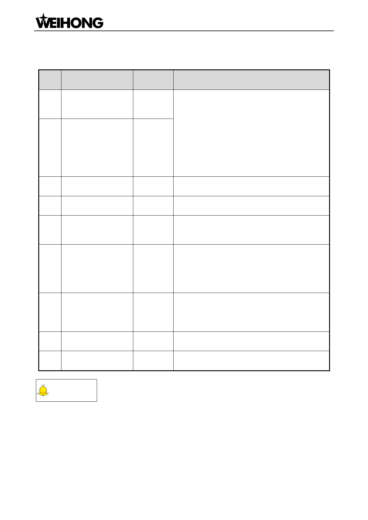
10.1.6. Parameter Setting of FUJI FALDIC-β Servo Driver
Para.
No.
Name
Command
01
numerator α
Value
Need
pulse
calculation
1~32767
Need
Command
pulse
02
calculation
denominator β
1~32767
03 Pulse string input form 0
Direction of rotation
04
0 or 1
switch
CONT1
10
distribution
signal
1
CONT2
11
distribution
signal
2
OUT1
signal
15
1
distribution
Parameter
27
write-protection
0 or 1
74 CONT Always ON 1 1
Description
Command pulse numerator and denominator are
also equal to those of the electronic gear ratio.
α/ β=encoder resolution× pulse equivalent×
mechanical deceleration ratio / screw pitch.
Typical value: encoder resolution 65536, pitch 5mm,
pulse equivalent 0.001, mechanical deceleration
ratio 1,
α / β=65536×0.001 / 5=8192 / 625,
So α=8192, β=625.
Set the input mode of pulse string as: instruction +
symbol, that is ‘pulse + direction’.
Set 0: Positive direction: Forward rotation (CCW);
Set 1: Positive direction: Reverse rotation (CW).
CONT1 is distributed as RUN (i.e. SON); if not
distributed, CONT1 will be auto ON if there is no
alarming when powered.
CONT2 is distributed as RST (i.e. servo alarming
clearance CLR).
When 12, 13, 14 are 0, that is CONT3, CONT4 and
CONT5 can’t be distributed as OT (over-travel) or
EMG (external emergency stop).
Set 1, OUT1 is distributed as a-contact point of
alarming output;
Set 2, OUT1 is distributed as b-contact point of
alarming detection.
Set 0, write-enable.
Set 1, write-protected.
Its initial value is 0, and it is set “1” here to enable
servo (RUN).
CAUTION
FUJI servo has no braking signal wire, so there is no need to set the parameters related to braking; you only
need to provide 24V brake power to pin Br (lead wire 5 and 6) of motor with braking.
「92」Driver
 EasyRoute CNC Control Panel Manufacture Manual")
 EasyRoute CNC Control Panel Manufacture Manual")
 EasyRoute CNC Control Panel Manufacture Manual")
 EasyRoute CNC Control Panel Manufacture Manual")
 EasyRoute CNC Control Panel Manufacture Manual")
 EasyRoute CNC Control Panel Manufacture Manual")
 EasyRoute CNC Control Panel Manufacture Manual")
 EasyRoute CNC Control Panel Manufacture Manual")
 EasyRoute CNC Control Panel Manufacture Manual")
 EasyRoute CNC Control Panel Manufacture Manual")
 EasyRoute CNC Control Panel Manufacture Manual")
 EasyRoute CNC Control Panel Manufacture Manual")
 EasyRoute CNC Control Panel Manufacture Manual")
 EasyRoute CNC Control Panel Manufacture Manual")
 EasyRoute CNC Control Panel Manufacture Manual")
 EasyRoute CNC Control Panel Manufacture Manual")
 EasyRoute CNC Control Panel Manufacture Manual")
 EasyRoute CNC Control Panel Manufacture Manual")
 EasyRoute CNC Control Panel Manufacture Manual")
 EasyRoute CNC Control Panel Manufacture Manual")
 EasyRoute CNC Control Panel Manufacture Manual")
 EasyRoute CNC Control Panel Manufacture Manual")
 EasyRoute CNC Control Panel Manufacture Manual")
 EasyRoute CNC Control Panel Manufacture Manual")
 EasyRoute CNC Control Panel Manufacture Manual")
 EasyRoute CNC Control Panel Manufacture Manual")
 EasyRoute CNC Control Panel Manufacture Manual")
 EasyRoute CNC Control Panel Manufacture Manual")
 EasyRoute CNC Control Panel Manufacture Manual")
 EasyRoute CNC Control Panel Manufacture Manual")
 EasyRoute CNC Control Panel Manufacture Manual")
 EasyRoute CNC Control Panel Manufacture Manual")
 EasyRoute CNC Control Panel Manufacture Manual")
 EasyRoute CNC Control Panel Manufacture Manual")
 EasyRoute CNC Control Panel Manufacture Manual")
 EasyRoute CNC Control Panel Manufacture Manual")
 EasyRoute CNC Control Panel Manufacture Manual")
 EasyRoute CNC Control Panel Manufacture Manual")
 EasyRoute CNC Control Panel Manufacture Manual")
 EasyRoute CNC Control Panel Manufacture Manual")
 EasyRoute CNC Control Panel Manufacture Manual")
 EasyRoute CNC Control Panel Manufacture Manual")
 EasyRoute CNC Control Panel Manufacture Manual")
 EasyRoute CNC Control Panel Manufacture Manual")
 EasyRoute CNC Control Panel Manufacture Manual")
 EasyRoute CNC Control Panel Manufacture Manual")
 EasyRoute CNC Control Panel Manufacture Manual")
 EasyRoute CNC Control Panel Manufacture Manual")
 EasyRoute CNC Control Panel Manufacture Manual")
 EasyRoute CNC Control Panel Manufacture Manual")
 EasyRoute CNC Control Panel Manufacture Manual")
 EasyRoute CNC Control Panel Manufacture Manual")
 EasyRoute CNC Control Panel Manufacture Manual")
 EasyRoute CNC Control Panel Manufacture Manual")
 EasyRoute CNC Control Panel Manufacture Manual")
 EasyRoute CNC Control Panel Manufacture Manual")
 EasyRoute CNC Control Panel Manufacture Manual")
 EasyRoute CNC Control Panel Manufacture Manual")
 EasyRoute CNC Control Panel Manufacture Manual")
 EasyRoute CNC Control Panel Manufacture Manual")
 EasyRoute CNC Control Panel Manufacture Manual")
 EasyRoute CNC Control Panel Manufacture Manual")
 EasyRoute CNC Control Panel Manufacture Manual")
 EasyRoute CNC Control Panel Manufacture Manual")
 EasyRoute CNC Control Panel Manufacture Manual")
 EasyRoute CNC Control Panel Manufacture Manual")
 EasyRoute CNC Control Panel Manufacture Manual")
 EasyRoute CNC Control Panel Manufacture Manual")
 EasyRoute CNC Control Panel Manufacture Manual")
 EasyRoute CNC Control Panel Manufacture Manual")
 EasyRoute CNC Control Panel Manufacture Manual")
 EasyRoute CNC Control Panel Manufacture Manual")
 EasyRoute CNC Control Panel Manufacture Manual")
 EasyRoute CNC Control Panel Manufacture Manual")
 EasyRoute CNC Control Panel Manufacture Manual")
 EasyRoute CNC Control Panel Manufacture Manual")
 EasyRoute CNC Control Panel Manufacture Manual")
 EasyRoute CNC Control Panel Manufacture Manual")
 EasyRoute CNC Control Panel Manufacture Manual")
 EasyRoute CNC Control Panel Manufacture Manual")
 EasyRoute CNC Control Panel Manufacture Manual")
 EasyRoute CNC Control Panel Manufacture Manual")
 EasyRoute CNC Control Panel Manufacture Manual")
 EasyRoute CNC Control Panel Manufacture Manual")
 EasyRoute CNC Control Panel Manufacture Manual")
 EasyRoute CNC Control Panel Manufacture Manual")
 EasyRoute CNC Control Panel Manufacture Manual")
 EasyRoute CNC Control Panel Manufacture Manual")
 EasyRoute CNC Control Panel Manufacture Manual")
 EasyRoute CNC Control Panel Manufacture Manual")
 EasyRoute CNC Control Panel Manufacture Manual")
 EasyRoute CNC Control Panel Manufacture Manual")
 EasyRoute CNC Control Panel Manufacture Manual")
 EasyRoute CNC Control Panel Manufacture Manual")
 EasyRoute CNC Control Panel Manufacture Manual")
 EasyRoute CNC Control Panel Manufacture Manual")
 EasyRoute CNC Control Panel Manufacture Manual")
 EasyRoute CNC Control Panel Manufacture Manual")
 EasyRoute CNC Control Panel Manufacture Manual")
 EasyRoute CNC Control Panel Manufacture Manual")
 EasyRoute CNC Control Panel Manufacture Manual")
 EasyRoute CNC Control Panel Manufacture Manual")
 EasyRoute CNC Control Panel Manufacture Manual")
 EasyRoute CNC Control Panel Manufacture Manual")
 EasyRoute CNC Control Panel Manufacture Manual")
 EasyRoute CNC Control Panel Manufacture Manual")
 EasyRoute CNC Control Panel Manufacture Manual")
 EasyRoute CNC Control Panel Manufacture Manual")
 EasyRoute CNC Control Panel Manufacture Manual")
 EasyRoute CNC Control Panel Manufacture Manual")
 EasyRoute CNC Control Panel Manufacture Manual")
 EasyRoute CNC Control Panel Manufacture Manual")
 EasyRoute CNC Control Panel Manufacture Manual")
 EasyRoute CNC Control Panel Manufacture Manual")