
- You are here:
- AM.CO.ZABuythisCNC Utilities Homepage
- EasyRoute-CNC-Router
- EasyRoute CNC Control Panel Manufacture Manual.pdf
- Page 111 of 114
Specialized Concentrated Focused
connected to relay to control brake.
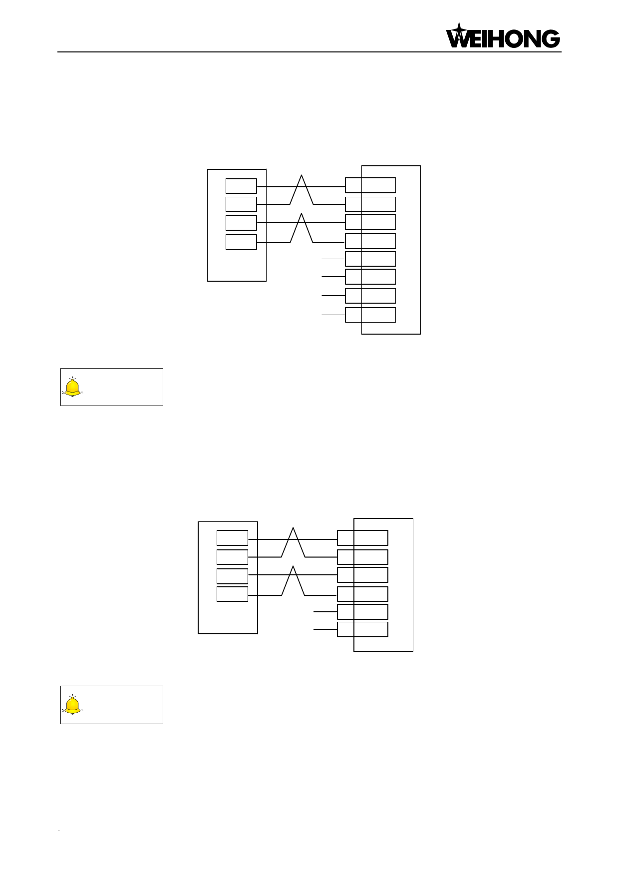
10.2.6. Wiring Diagram of MITSUBISHI MR-E Servo Driver
NK105 Control Box
MITSUBISHI MR _E
Servo Driver
D-
D+
P-
P+
24V
COM
Z-axis Brake W ire (Red)
Z-axis Brake W ire (Black)
24 NG
25 NP
22 PG
23 PP
1 VIN
13 SG
12 MBR
13 SG
Fig. 10-7 Wiring diagram of NK105 and MITSUBISHI MR-E servo driver
CAUTION
Wirings of X axis, Y axis, and Z axis are the same. Only Z axis has two brake signal lines which can be
connected to relay to control brake.
10.2.7. Wiring Diagram of FUJI FALDIC-β Servo Driver
NK105 Control
Box
D-
D+
P-
P+
24V
COM
FUJI FALDIC-ß
Servo Driver
21 *CB
20 CB
8 *C A
7 CA
1 P24
14 M24
Fig. 10-8 Wiring diagram of NK105 and FUJI FALDIC-β servo driver
CAUTION
Wirings of X axis, Y axis, and Z axis are the same, and the brake of Z axis is internally controlled.
Driver「99」
 EasyRoute CNC Control Panel Manufacture Manual")
 EasyRoute CNC Control Panel Manufacture Manual")
 EasyRoute CNC Control Panel Manufacture Manual")
 EasyRoute CNC Control Panel Manufacture Manual")
 EasyRoute CNC Control Panel Manufacture Manual")
 EasyRoute CNC Control Panel Manufacture Manual")
 EasyRoute CNC Control Panel Manufacture Manual")
 EasyRoute CNC Control Panel Manufacture Manual")
 EasyRoute CNC Control Panel Manufacture Manual")
 EasyRoute CNC Control Panel Manufacture Manual")
 EasyRoute CNC Control Panel Manufacture Manual")
 EasyRoute CNC Control Panel Manufacture Manual")
 EasyRoute CNC Control Panel Manufacture Manual")
 EasyRoute CNC Control Panel Manufacture Manual")
 EasyRoute CNC Control Panel Manufacture Manual")
 EasyRoute CNC Control Panel Manufacture Manual")
 EasyRoute CNC Control Panel Manufacture Manual")
 EasyRoute CNC Control Panel Manufacture Manual")
 EasyRoute CNC Control Panel Manufacture Manual")
 EasyRoute CNC Control Panel Manufacture Manual")
 EasyRoute CNC Control Panel Manufacture Manual")
 EasyRoute CNC Control Panel Manufacture Manual")
 EasyRoute CNC Control Panel Manufacture Manual")
 EasyRoute CNC Control Panel Manufacture Manual")
 EasyRoute CNC Control Panel Manufacture Manual")
 EasyRoute CNC Control Panel Manufacture Manual")
 EasyRoute CNC Control Panel Manufacture Manual")
 EasyRoute CNC Control Panel Manufacture Manual")
 EasyRoute CNC Control Panel Manufacture Manual")
 EasyRoute CNC Control Panel Manufacture Manual")
 EasyRoute CNC Control Panel Manufacture Manual")
 EasyRoute CNC Control Panel Manufacture Manual")
 EasyRoute CNC Control Panel Manufacture Manual")
 EasyRoute CNC Control Panel Manufacture Manual")
 EasyRoute CNC Control Panel Manufacture Manual")
 EasyRoute CNC Control Panel Manufacture Manual")
 EasyRoute CNC Control Panel Manufacture Manual")
 EasyRoute CNC Control Panel Manufacture Manual")
 EasyRoute CNC Control Panel Manufacture Manual")
 EasyRoute CNC Control Panel Manufacture Manual")
 EasyRoute CNC Control Panel Manufacture Manual")
 EasyRoute CNC Control Panel Manufacture Manual")
 EasyRoute CNC Control Panel Manufacture Manual")
 EasyRoute CNC Control Panel Manufacture Manual")
 EasyRoute CNC Control Panel Manufacture Manual")
 EasyRoute CNC Control Panel Manufacture Manual")
 EasyRoute CNC Control Panel Manufacture Manual")
 EasyRoute CNC Control Panel Manufacture Manual")
 EasyRoute CNC Control Panel Manufacture Manual")
 EasyRoute CNC Control Panel Manufacture Manual")
 EasyRoute CNC Control Panel Manufacture Manual")
 EasyRoute CNC Control Panel Manufacture Manual")
 EasyRoute CNC Control Panel Manufacture Manual")
 EasyRoute CNC Control Panel Manufacture Manual")
 EasyRoute CNC Control Panel Manufacture Manual")
 EasyRoute CNC Control Panel Manufacture Manual")
 EasyRoute CNC Control Panel Manufacture Manual")
 EasyRoute CNC Control Panel Manufacture Manual")
 EasyRoute CNC Control Panel Manufacture Manual")
 EasyRoute CNC Control Panel Manufacture Manual")
 EasyRoute CNC Control Panel Manufacture Manual")
 EasyRoute CNC Control Panel Manufacture Manual")
 EasyRoute CNC Control Panel Manufacture Manual")
 EasyRoute CNC Control Panel Manufacture Manual")
 EasyRoute CNC Control Panel Manufacture Manual")
 EasyRoute CNC Control Panel Manufacture Manual")
 EasyRoute CNC Control Panel Manufacture Manual")
 EasyRoute CNC Control Panel Manufacture Manual")
 EasyRoute CNC Control Panel Manufacture Manual")
 EasyRoute CNC Control Panel Manufacture Manual")
 EasyRoute CNC Control Panel Manufacture Manual")
 EasyRoute CNC Control Panel Manufacture Manual")
 EasyRoute CNC Control Panel Manufacture Manual")
 EasyRoute CNC Control Panel Manufacture Manual")
 EasyRoute CNC Control Panel Manufacture Manual")
 EasyRoute CNC Control Panel Manufacture Manual")
 EasyRoute CNC Control Panel Manufacture Manual")
 EasyRoute CNC Control Panel Manufacture Manual")
 EasyRoute CNC Control Panel Manufacture Manual")
 EasyRoute CNC Control Panel Manufacture Manual")
 EasyRoute CNC Control Panel Manufacture Manual")
 EasyRoute CNC Control Panel Manufacture Manual")
 EasyRoute CNC Control Panel Manufacture Manual")
 EasyRoute CNC Control Panel Manufacture Manual")
 EasyRoute CNC Control Panel Manufacture Manual")
 EasyRoute CNC Control Panel Manufacture Manual")
 EasyRoute CNC Control Panel Manufacture Manual")
 EasyRoute CNC Control Panel Manufacture Manual")
 EasyRoute CNC Control Panel Manufacture Manual")
 EasyRoute CNC Control Panel Manufacture Manual")
 EasyRoute CNC Control Panel Manufacture Manual")
 EasyRoute CNC Control Panel Manufacture Manual")
 EasyRoute CNC Control Panel Manufacture Manual")
 EasyRoute CNC Control Panel Manufacture Manual")
 EasyRoute CNC Control Panel Manufacture Manual")
 EasyRoute CNC Control Panel Manufacture Manual")
 EasyRoute CNC Control Panel Manufacture Manual")
 EasyRoute CNC Control Panel Manufacture Manual")
 EasyRoute CNC Control Panel Manufacture Manual")
 EasyRoute CNC Control Panel Manufacture Manual")
 EasyRoute CNC Control Panel Manufacture Manual")
 EasyRoute CNC Control Panel Manufacture Manual")
 EasyRoute CNC Control Panel Manufacture Manual")
 EasyRoute CNC Control Panel Manufacture Manual")
 EasyRoute CNC Control Panel Manufacture Manual")
 EasyRoute CNC Control Panel Manufacture Manual")
 EasyRoute CNC Control Panel Manufacture Manual")
 EasyRoute CNC Control Panel Manufacture Manual")
 EasyRoute CNC Control Panel Manufacture Manual")
 EasyRoute CNC Control Panel Manufacture Manual")
 EasyRoute CNC Control Panel Manufacture Manual")
 EasyRoute CNC Control Panel Manufacture Manual")
 EasyRoute CNC Control Panel Manufacture Manual")
 EasyRoute CNC Control Panel Manufacture Manual")