
- You are here:
- AM.CO.ZABuythisCNC Utilities Homepage
- EasyRoute-CNC-Router
- EasyRoute CNC Control Panel Manufacture Manual.pdf
- Page 108 of 114
Specialized Concentrated Focused
10.2.Wiring Diagram of NK105 and Driver
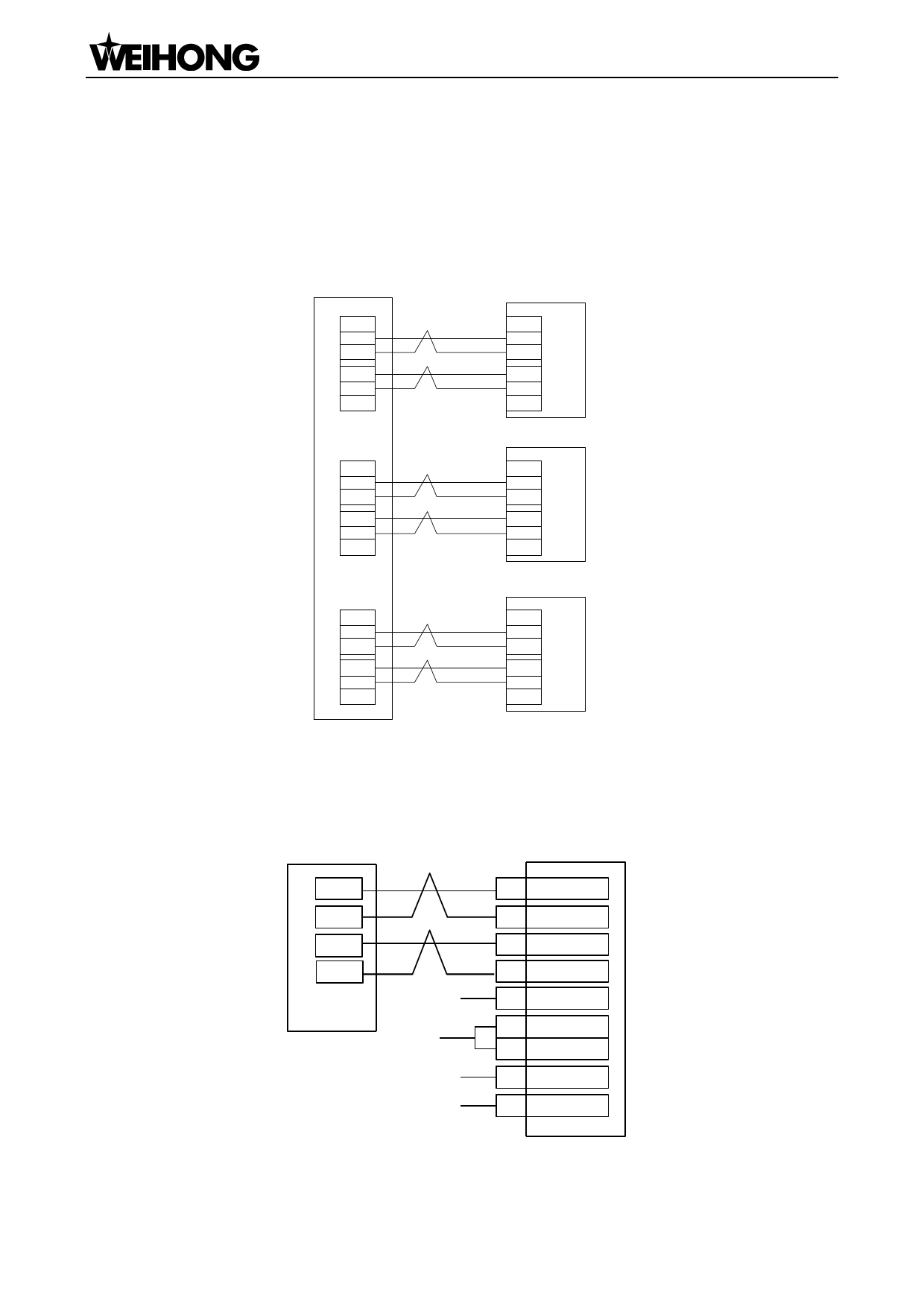
10.2.1. Wiring Diagram of NK105 and Differential Input Stepping
Driver
NK105 Control Box
X-axis Stepping Driver
XD+
D+
XD-
D-
XP+
P+
XP-
P-
YD-+
YD+-
YP-+
YP+-
+5V
ZD-+
ZD+-
ZP-+
ZP+-
+5V
Y-axis Stepping Driver
+CO
MD+
(OPTO)
DI-R
P+
CP-P
Z-axis Stepping Driver
+CO
MD+ (OPTO)
DI-R
P+
CP-P
Note: twisted pair adopted for differential signal
Fig. 10-1 Wiring of NK105 control box and differential input stepping driver
10.2.2. Wiring Diagram of WISE Servo Driver
NK105 Control Box
D-
D+
P-
P+
24V
COM
Z-axis Brake Wire(Red)
Z-axis Brake Wire(Black)
WISE Servo
12 /SIGN
11 SIGN
8 /PULS
7 PULS
47 +24VIN
40 SRV-ON
1 GND
29 BRK-OFF+
30 BRK-OFF-
Note: twisted pair adopted for differential signal
Fig. 10-2 Wiring diagram of NK105 and Wise servo driver
「96」Driver
 EasyRoute CNC Control Panel Manufacture Manual")
 EasyRoute CNC Control Panel Manufacture Manual")
 EasyRoute CNC Control Panel Manufacture Manual")
 EasyRoute CNC Control Panel Manufacture Manual")
 EasyRoute CNC Control Panel Manufacture Manual")
 EasyRoute CNC Control Panel Manufacture Manual")
 EasyRoute CNC Control Panel Manufacture Manual")
 EasyRoute CNC Control Panel Manufacture Manual")
 EasyRoute CNC Control Panel Manufacture Manual")
 EasyRoute CNC Control Panel Manufacture Manual")
 EasyRoute CNC Control Panel Manufacture Manual")
 EasyRoute CNC Control Panel Manufacture Manual")
 EasyRoute CNC Control Panel Manufacture Manual")
 EasyRoute CNC Control Panel Manufacture Manual")
 EasyRoute CNC Control Panel Manufacture Manual")
 EasyRoute CNC Control Panel Manufacture Manual")
 EasyRoute CNC Control Panel Manufacture Manual")
 EasyRoute CNC Control Panel Manufacture Manual")
 EasyRoute CNC Control Panel Manufacture Manual")
 EasyRoute CNC Control Panel Manufacture Manual")
 EasyRoute CNC Control Panel Manufacture Manual")
 EasyRoute CNC Control Panel Manufacture Manual")
 EasyRoute CNC Control Panel Manufacture Manual")
 EasyRoute CNC Control Panel Manufacture Manual")
 EasyRoute CNC Control Panel Manufacture Manual")
 EasyRoute CNC Control Panel Manufacture Manual")
 EasyRoute CNC Control Panel Manufacture Manual")
 EasyRoute CNC Control Panel Manufacture Manual")
 EasyRoute CNC Control Panel Manufacture Manual")
 EasyRoute CNC Control Panel Manufacture Manual")
 EasyRoute CNC Control Panel Manufacture Manual")
 EasyRoute CNC Control Panel Manufacture Manual")
 EasyRoute CNC Control Panel Manufacture Manual")
 EasyRoute CNC Control Panel Manufacture Manual")
 EasyRoute CNC Control Panel Manufacture Manual")
 EasyRoute CNC Control Panel Manufacture Manual")
 EasyRoute CNC Control Panel Manufacture Manual")
 EasyRoute CNC Control Panel Manufacture Manual")
 EasyRoute CNC Control Panel Manufacture Manual")
 EasyRoute CNC Control Panel Manufacture Manual")
 EasyRoute CNC Control Panel Manufacture Manual")
 EasyRoute CNC Control Panel Manufacture Manual")
 EasyRoute CNC Control Panel Manufacture Manual")
 EasyRoute CNC Control Panel Manufacture Manual")
 EasyRoute CNC Control Panel Manufacture Manual")
 EasyRoute CNC Control Panel Manufacture Manual")
 EasyRoute CNC Control Panel Manufacture Manual")
 EasyRoute CNC Control Panel Manufacture Manual")
 EasyRoute CNC Control Panel Manufacture Manual")
 EasyRoute CNC Control Panel Manufacture Manual")
 EasyRoute CNC Control Panel Manufacture Manual")
 EasyRoute CNC Control Panel Manufacture Manual")
 EasyRoute CNC Control Panel Manufacture Manual")
 EasyRoute CNC Control Panel Manufacture Manual")
 EasyRoute CNC Control Panel Manufacture Manual")
 EasyRoute CNC Control Panel Manufacture Manual")
 EasyRoute CNC Control Panel Manufacture Manual")
 EasyRoute CNC Control Panel Manufacture Manual")
 EasyRoute CNC Control Panel Manufacture Manual")
 EasyRoute CNC Control Panel Manufacture Manual")
 EasyRoute CNC Control Panel Manufacture Manual")
 EasyRoute CNC Control Panel Manufacture Manual")
 EasyRoute CNC Control Panel Manufacture Manual")
 EasyRoute CNC Control Panel Manufacture Manual")
 EasyRoute CNC Control Panel Manufacture Manual")
 EasyRoute CNC Control Panel Manufacture Manual")
 EasyRoute CNC Control Panel Manufacture Manual")
 EasyRoute CNC Control Panel Manufacture Manual")
 EasyRoute CNC Control Panel Manufacture Manual")
 EasyRoute CNC Control Panel Manufacture Manual")
 EasyRoute CNC Control Panel Manufacture Manual")
 EasyRoute CNC Control Panel Manufacture Manual")
 EasyRoute CNC Control Panel Manufacture Manual")
 EasyRoute CNC Control Panel Manufacture Manual")
 EasyRoute CNC Control Panel Manufacture Manual")
 EasyRoute CNC Control Panel Manufacture Manual")
 EasyRoute CNC Control Panel Manufacture Manual")
 EasyRoute CNC Control Panel Manufacture Manual")
 EasyRoute CNC Control Panel Manufacture Manual")
 EasyRoute CNC Control Panel Manufacture Manual")
 EasyRoute CNC Control Panel Manufacture Manual")
 EasyRoute CNC Control Panel Manufacture Manual")
 EasyRoute CNC Control Panel Manufacture Manual")
 EasyRoute CNC Control Panel Manufacture Manual")
 EasyRoute CNC Control Panel Manufacture Manual")
 EasyRoute CNC Control Panel Manufacture Manual")
 EasyRoute CNC Control Panel Manufacture Manual")
 EasyRoute CNC Control Panel Manufacture Manual")
 EasyRoute CNC Control Panel Manufacture Manual")
 EasyRoute CNC Control Panel Manufacture Manual")
 EasyRoute CNC Control Panel Manufacture Manual")
 EasyRoute CNC Control Panel Manufacture Manual")
 EasyRoute CNC Control Panel Manufacture Manual")
 EasyRoute CNC Control Panel Manufacture Manual")
 EasyRoute CNC Control Panel Manufacture Manual")
 EasyRoute CNC Control Panel Manufacture Manual")
 EasyRoute CNC Control Panel Manufacture Manual")
 EasyRoute CNC Control Panel Manufacture Manual")
 EasyRoute CNC Control Panel Manufacture Manual")
 EasyRoute CNC Control Panel Manufacture Manual")
 EasyRoute CNC Control Panel Manufacture Manual")
 EasyRoute CNC Control Panel Manufacture Manual")
 EasyRoute CNC Control Panel Manufacture Manual")
 EasyRoute CNC Control Panel Manufacture Manual")
 EasyRoute CNC Control Panel Manufacture Manual")
 EasyRoute CNC Control Panel Manufacture Manual")
 EasyRoute CNC Control Panel Manufacture Manual")
 EasyRoute CNC Control Panel Manufacture Manual")
 EasyRoute CNC Control Panel Manufacture Manual")
 EasyRoute CNC Control Panel Manufacture Manual")
 EasyRoute CNC Control Panel Manufacture Manual")
 EasyRoute CNC Control Panel Manufacture Manual")
 EasyRoute CNC Control Panel Manufacture Manual")
 EasyRoute CNC Control Panel Manufacture Manual")