CypCut Laser Cutting Control System
4
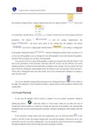
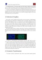
Each of the seventeen color square buttons corresponds to a layer, and when a graph is selected, the
selected graph can be moved to the specified layer by clicking these buttons, when no graphs are
selected, it means to set the default layer for the next drawing by clicking these buttons. The first
white square indicates a special layer. When “un-exported Layer” is displayed, the graph on this layer
will be shown in white and it cannot be processed. The last two layers are layers of first processing
and last processing.
There are three scrolling displayed ribbon text windows below the interface. The left one is “Draw
Window”. The related prompting messages of all the draw instructions or input message will be
shown here. The middle one is “System Window”, and other system messages will be displayed here
except drawing. Each message has time mark and they will be shown in different colors according to
the importance of the message, which includes prompting, warning and error and so on. The right one
is “Alarm Window”, in which all the alarm message will be displayed in red background and white
text.
There is the Status Bar at the bottom of the interface, which can show different prompting
messages according to different operations. There are some basic messages of drawn processing
graphics at the left, and some commonly used messages at the right of the status bar, including the
location of the mouse, processing status and the location of the laser head. The latter one is the
fine-tuning distance parameter, which can move the graphs quickly by using direction keys. The final
show is the type of control card.
The rectangular area at the right of the interface is called “Console”, and most common operations
related to control will be done here. From top to bottom one by one are choices of coordinate system,
manual control, work control, processing options and processing count.
1.3.3 Toolbar
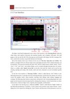
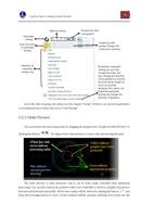
The toolbar of CypCut uses a style called Ribbon. It puts the common functions by column and
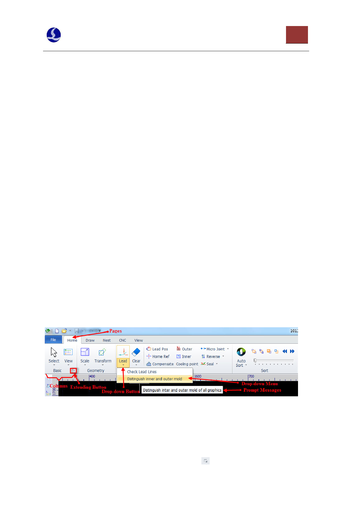
area, and also applies many large-size buttons for easy operation. The photo below will help you to
understand this new toolbar:
The whole toolbar is divided into five “pages”, which can be selected by the five menus “Home”,
“Draw”, “Nest”, “CNC” and “View”. When selecting each menu, the pages related to the selected
contents will appear. Furthermore, the page “Being Processed” will appear during processing and it
cannot be switched to other pages before stopping.
The toolbar of each page will be arranged again in multiple “Columns” according to the functions,
such as “Base operation” and “Geometric transformation” and so on. The first buttons of the general
columns are all in large size, and there is a small button“ ” at the lower right corners of some

