23 CypCut Laser Cutting Control System
3.3 Micro Joint
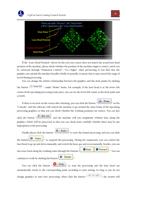
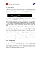
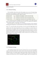
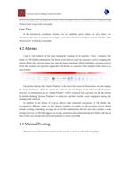
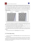
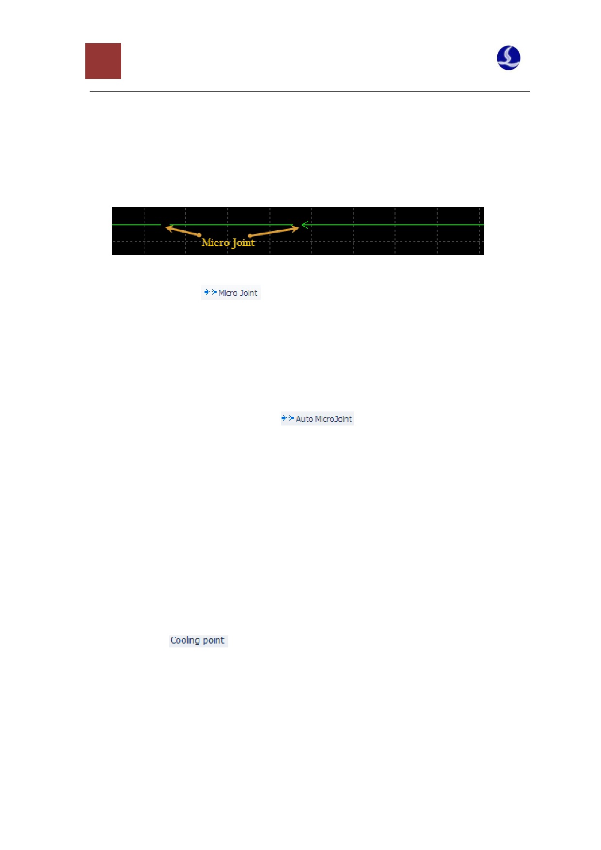
“Micro Joint” can be used to insert a micro joint into the track which will not be cut. When cutting
to here, the laser will be closed; however, whether closing the gas and the follower is determined by
the related parameters of short-distance vacant move during cutting. Micro joint is shown as a gap on
the drawing board. As shown below:
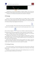
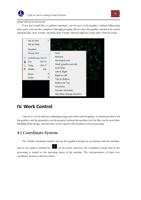
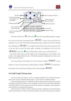
You can add a micro joint by clicking at the position of the graphics needed to add micro joints
by clicking the button “
” on the toolbar,. You can insert multiple micro joints by
clicking continuously until you press ESC to cancel the command or switch it to other commands.
You can not only click on the graphics but also click on the compensated track to insert micro joints.
Please directly enter the length parameter of the micro joint in the drawing window at the
bottom of the software, and the new parameters will be valid for the following operations after
setting.
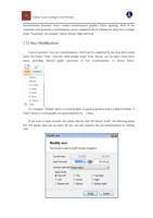
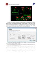
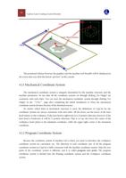
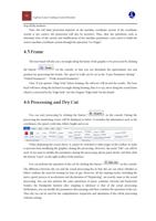
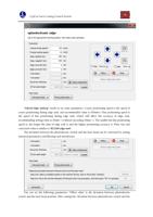
Except adding the micro joints manually, CypCut also provides the function of inserting micro
joints automatically. Users can click the “
” button by clicking the small triangle
button in the right corner of "Micro Joint", set the parameters in the popped dialog box, and then
confirm it. You can select “adding by quantity”, for example, you can add ten micro joints to each
graphic; or “adding by distance”; for example, you can insert a micro joint every 100mm.
The graphics may be divided into paragraphs through “Micro joint”. If you want to modify some
separation section alone, you can click the "explode MicroJoint" button under the "Micro Joint"
drop-down menu. Unclosed graphics after “Micro Joint” operation will be regarded as a separate
entity for modification.
In order to clear the micro joints, users need to select the needed graphics, then click the “Clear”
button and choose “Clear Micro Joint”.
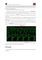
3.4 Cooling point
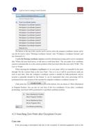
Click the "
" button in the “Home” menu. When click on the corresponding
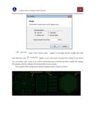
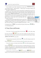
position in the graphics, you can set a cooling point at that location. When cutting is implemented to
the cooling point, laser will be off and blow will be delayed according to cooling point corresponding
settings in the global parameter. Later, laser will be on and operate normal cutting. Cooling point
displayed as a solid point in the drawing board, as shown below:

