
GigE Area Scan Camera User Manual
Chapter 4 I/O Connector and Indicator
4.1 Power and I/O Connector
The device has a 6-pin P7 connector or 12-pin P10 connector as the power and I/O
connector that provides power supply, input/output signal and serial port function.
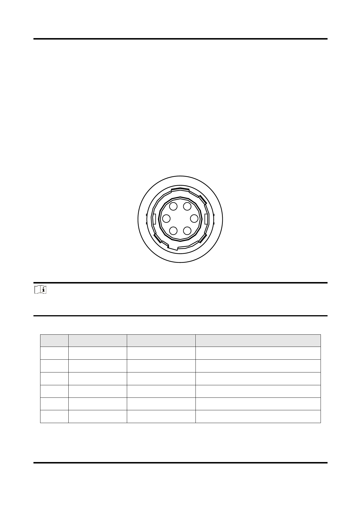
4.1.1 6-Pin P7 Connector
The 6-pin P7 connector is applicable to type I, type II, type III, and type IV devices.
16
2
5
3 4
Figure 4-1 6-Pin P7 Connector
Note
Refer to the table below and the label attached to the power and I/O cable to wire the
device.
No.
1
2
3
4
5
6
Table 4-1 Pin Definitions of 6-Pin P7 Connector
Signal
I/O Signal Source
Description
DC_PWR
--
Device’s power supply
OPTO_IN
Line 0+
Opto-isolated input
GPIO
Line 2+
Can be configured as input or output
OPTO_OUT
Line 1+
Opto-isolated output
OPTO_GND
Line 0-/1-
Opto-isolated signal ground
GND
Line 2-
Device’s power supply ground
9
 Hikrobot GigE Area Scan Camera User Manual")
 Hikrobot GigE Area Scan Camera User Manual")
 Hikrobot GigE Area Scan Camera User Manual")
 Hikrobot GigE Area Scan Camera User Manual")
 Hikrobot GigE Area Scan Camera User Manual")
 Hikrobot GigE Area Scan Camera User Manual")
 Hikrobot GigE Area Scan Camera User Manual")
 Hikrobot GigE Area Scan Camera User Manual")
 Hikrobot GigE Area Scan Camera User Manual")
 Hikrobot GigE Area Scan Camera User Manual")
 Hikrobot GigE Area Scan Camera User Manual")
 Hikrobot GigE Area Scan Camera User Manual")
 Hikrobot GigE Area Scan Camera User Manual")
 Hikrobot GigE Area Scan Camera User Manual")
 Hikrobot GigE Area Scan Camera User Manual")
 Hikrobot GigE Area Scan Camera User Manual")
 Hikrobot GigE Area Scan Camera User Manual")
 Hikrobot GigE Area Scan Camera User Manual")
 Hikrobot GigE Area Scan Camera User Manual")
 Hikrobot GigE Area Scan Camera User Manual")
 Hikrobot GigE Area Scan Camera User Manual")
 Hikrobot GigE Area Scan Camera User Manual")
 Hikrobot GigE Area Scan Camera User Manual")
 Hikrobot GigE Area Scan Camera User Manual")
 Hikrobot GigE Area Scan Camera User Manual")
 Hikrobot GigE Area Scan Camera User Manual")
 Hikrobot GigE Area Scan Camera User Manual")
 Hikrobot GigE Area Scan Camera User Manual")
 Hikrobot GigE Area Scan Camera User Manual")
 Hikrobot GigE Area Scan Camera User Manual")
 Hikrobot GigE Area Scan Camera User Manual")
 Hikrobot GigE Area Scan Camera User Manual")
 Hikrobot GigE Area Scan Camera User Manual")
 Hikrobot GigE Area Scan Camera User Manual")
 Hikrobot GigE Area Scan Camera User Manual")
 Hikrobot GigE Area Scan Camera User Manual")
 Hikrobot GigE Area Scan Camera User Manual")
 Hikrobot GigE Area Scan Camera User Manual")
 Hikrobot GigE Area Scan Camera User Manual")
 Hikrobot GigE Area Scan Camera User Manual")
 Hikrobot GigE Area Scan Camera User Manual")
 Hikrobot GigE Area Scan Camera User Manual")
 Hikrobot GigE Area Scan Camera User Manual")
 Hikrobot GigE Area Scan Camera User Manual")
 Hikrobot GigE Area Scan Camera User Manual")
 Hikrobot GigE Area Scan Camera User Manual")
 Hikrobot GigE Area Scan Camera User Manual")
 Hikrobot GigE Area Scan Camera User Manual")
 Hikrobot GigE Area Scan Camera User Manual")
 Hikrobot GigE Area Scan Camera User Manual")
 Hikrobot GigE Area Scan Camera User Manual")
 Hikrobot GigE Area Scan Camera User Manual")
 Hikrobot GigE Area Scan Camera User Manual")
 Hikrobot GigE Area Scan Camera User Manual")
 Hikrobot GigE Area Scan Camera User Manual")
 Hikrobot GigE Area Scan Camera User Manual")
 Hikrobot GigE Area Scan Camera User Manual")
 Hikrobot GigE Area Scan Camera User Manual")
 Hikrobot GigE Area Scan Camera User Manual")
 Hikrobot GigE Area Scan Camera User Manual")
 Hikrobot GigE Area Scan Camera User Manual")
 Hikrobot GigE Area Scan Camera User Manual")
 Hikrobot GigE Area Scan Camera User Manual")
 Hikrobot GigE Area Scan Camera User Manual")
 Hikrobot GigE Area Scan Camera User Manual")
 Hikrobot GigE Area Scan Camera User Manual")
 Hikrobot GigE Area Scan Camera User Manual")
 Hikrobot GigE Area Scan Camera User Manual")
 Hikrobot GigE Area Scan Camera User Manual")
 Hikrobot GigE Area Scan Camera User Manual")
 Hikrobot GigE Area Scan Camera User Manual")
 Hikrobot GigE Area Scan Camera User Manual")
 Hikrobot GigE Area Scan Camera User Manual")
 Hikrobot GigE Area Scan Camera User Manual")
 Hikrobot GigE Area Scan Camera User Manual")
 Hikrobot GigE Area Scan Camera User Manual")
 Hikrobot GigE Area Scan Camera User Manual")
 Hikrobot GigE Area Scan Camera User Manual")
 Hikrobot GigE Area Scan Camera User Manual")
 Hikrobot GigE Area Scan Camera User Manual")
 Hikrobot GigE Area Scan Camera User Manual")
 Hikrobot GigE Area Scan Camera User Manual")
 Hikrobot GigE Area Scan Camera User Manual")
 Hikrobot GigE Area Scan Camera User Manual")
 Hikrobot GigE Area Scan Camera User Manual")
 Hikrobot GigE Area Scan Camera User Manual")
 Hikrobot GigE Area Scan Camera User Manual")
 Hikrobot GigE Area Scan Camera User Manual")
 Hikrobot GigE Area Scan Camera User Manual")
 Hikrobot GigE Area Scan Camera User Manual")
 Hikrobot GigE Area Scan Camera User Manual")
 Hikrobot GigE Area Scan Camera User Manual")
 Hikrobot GigE Area Scan Camera User Manual")
 Hikrobot GigE Area Scan Camera User Manual")
 Hikrobot GigE Area Scan Camera User Manual")
 Hikrobot GigE Area Scan Camera User Manual")
 Hikrobot GigE Area Scan Camera User Manual")
 Hikrobot GigE Area Scan Camera User Manual")
 Hikrobot GigE Area Scan Camera User Manual")
 Hikrobot GigE Area Scan Camera User Manual")
 Hikrobot GigE Area Scan Camera User Manual")
 Hikrobot GigE Area Scan Camera User Manual")
 Hikrobot GigE Area Scan Camera User Manual")
 Hikrobot GigE Area Scan Camera User Manual")
 Hikrobot GigE Area Scan Camera User Manual")
 Hikrobot GigE Area Scan Camera User Manual")
 Hikrobot GigE Area Scan Camera User Manual")
 Hikrobot GigE Area Scan Camera User Manual")
 Hikrobot GigE Area Scan Camera User Manual")
 Hikrobot GigE Area Scan Camera User Manual")
 Hikrobot GigE Area Scan Camera User Manual")
 Hikrobot GigE Area Scan Camera User Manual")
 Hikrobot GigE Area Scan Camera User Manual")
 Hikrobot GigE Area Scan Camera User Manual")
 Hikrobot GigE Area Scan Camera User Manual")
 Hikrobot GigE Area Scan Camera User Manual")
 Hikrobot GigE Area Scan Camera User Manual")
 Hikrobot GigE Area Scan Camera User Manual")
 Hikrobot GigE Area Scan Camera User Manual")
 Hikrobot GigE Area Scan Camera User Manual")
 Hikrobot GigE Area Scan Camera User Manual")
 Hikrobot GigE Area Scan Camera User Manual")
 Hikrobot GigE Area Scan Camera User Manual")
 Hikrobot GigE Area Scan Camera User Manual")
 Hikrobot GigE Area Scan Camera User Manual")
 Hikrobot GigE Area Scan Camera User Manual")
 Hikrobot GigE Area Scan Camera User Manual")
 Hikrobot GigE Area Scan Camera User Manual")
 Hikrobot GigE Area Scan Camera User Manual")
 Hikrobot GigE Area Scan Camera User Manual")
 Hikrobot GigE Area Scan Camera User Manual")
 Hikrobot GigE Area Scan Camera User Manual")
 Hikrobot GigE Area Scan Camera User Manual")
 Hikrobot GigE Area Scan Camera User Manual")