
GigE Area Scan Camera User Manual
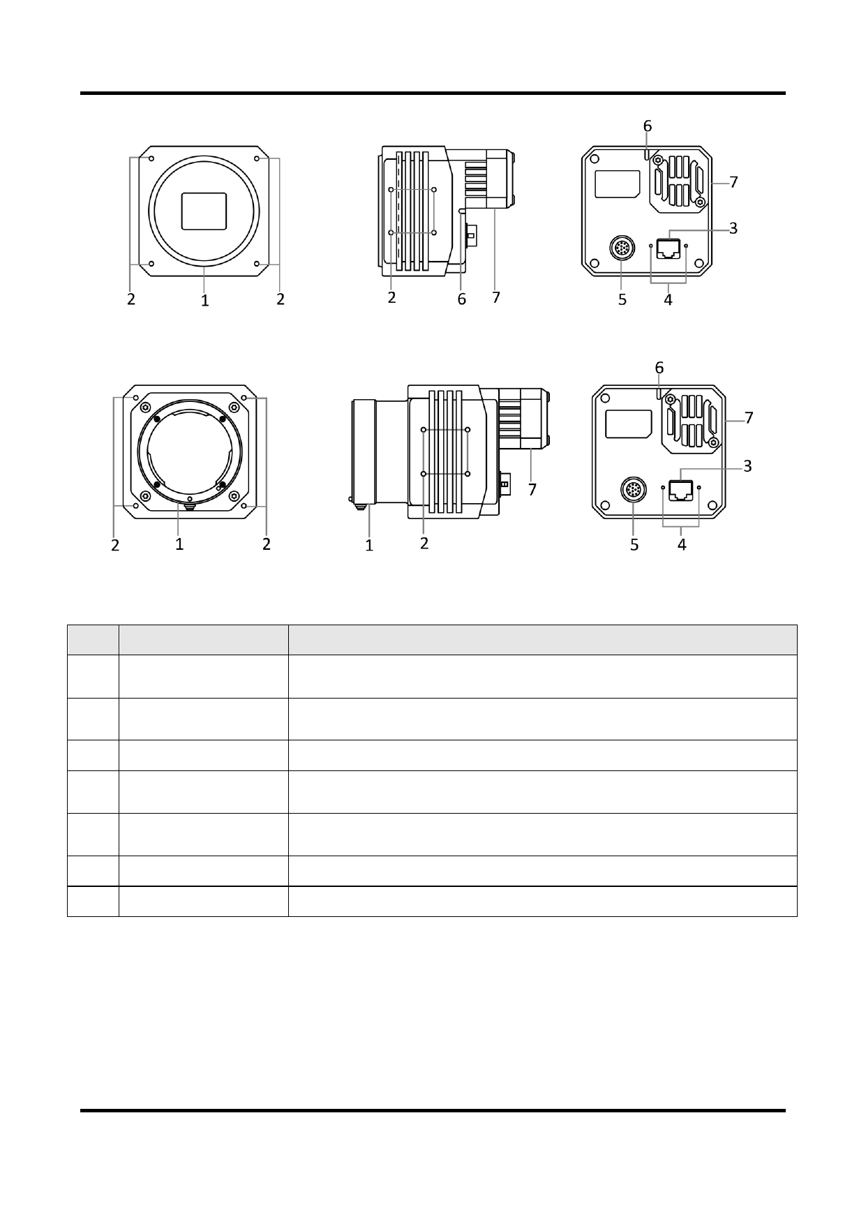
Figure 3-8 Appearance (Type VIII)
Figure 3-9 Appearance (Type IX)
Table 3-1 Component Description
No.
Component
Description
1 Lens Mount
2 Screw Hole
It is used to install the lens. Refer to the device’s specification
for specific lens mount information.
It is used to fix the device to the installation position. Refer to
the device’s specification for specific screw information.
3 GigE Interface
It refers to the GigE interface for transmitting data.
4
Screw Hole of GigE
Interface
It refers to the M2 screw hole for fixing the network cable.
5
Power and I/O It provides power supply, input/output signal and serial port
Connector
function.
6 LED Indicator
It indicates the device’s status.
7 Cooling Fan or TEC It is used to cool the device to ensure its normal operation.
8
 Hikrobot GigE Area Scan Camera User Manual")
 Hikrobot GigE Area Scan Camera User Manual")
 Hikrobot GigE Area Scan Camera User Manual")
 Hikrobot GigE Area Scan Camera User Manual")
 Hikrobot GigE Area Scan Camera User Manual")
 Hikrobot GigE Area Scan Camera User Manual")
 Hikrobot GigE Area Scan Camera User Manual")
 Hikrobot GigE Area Scan Camera User Manual")
 Hikrobot GigE Area Scan Camera User Manual")
 Hikrobot GigE Area Scan Camera User Manual")
 Hikrobot GigE Area Scan Camera User Manual")
 Hikrobot GigE Area Scan Camera User Manual")
 Hikrobot GigE Area Scan Camera User Manual")
 Hikrobot GigE Area Scan Camera User Manual")
 Hikrobot GigE Area Scan Camera User Manual")
 Hikrobot GigE Area Scan Camera User Manual")
 Hikrobot GigE Area Scan Camera User Manual")
 Hikrobot GigE Area Scan Camera User Manual")
 Hikrobot GigE Area Scan Camera User Manual")
 Hikrobot GigE Area Scan Camera User Manual")
 Hikrobot GigE Area Scan Camera User Manual")
 Hikrobot GigE Area Scan Camera User Manual")
 Hikrobot GigE Area Scan Camera User Manual")
 Hikrobot GigE Area Scan Camera User Manual")
 Hikrobot GigE Area Scan Camera User Manual")
 Hikrobot GigE Area Scan Camera User Manual")
 Hikrobot GigE Area Scan Camera User Manual")
 Hikrobot GigE Area Scan Camera User Manual")
 Hikrobot GigE Area Scan Camera User Manual")
 Hikrobot GigE Area Scan Camera User Manual")
 Hikrobot GigE Area Scan Camera User Manual")
 Hikrobot GigE Area Scan Camera User Manual")
 Hikrobot GigE Area Scan Camera User Manual")
 Hikrobot GigE Area Scan Camera User Manual")
 Hikrobot GigE Area Scan Camera User Manual")
 Hikrobot GigE Area Scan Camera User Manual")
 Hikrobot GigE Area Scan Camera User Manual")
 Hikrobot GigE Area Scan Camera User Manual")
 Hikrobot GigE Area Scan Camera User Manual")
 Hikrobot GigE Area Scan Camera User Manual")
 Hikrobot GigE Area Scan Camera User Manual")
 Hikrobot GigE Area Scan Camera User Manual")
 Hikrobot GigE Area Scan Camera User Manual")
 Hikrobot GigE Area Scan Camera User Manual")
 Hikrobot GigE Area Scan Camera User Manual")
 Hikrobot GigE Area Scan Camera User Manual")
 Hikrobot GigE Area Scan Camera User Manual")
 Hikrobot GigE Area Scan Camera User Manual")
 Hikrobot GigE Area Scan Camera User Manual")
 Hikrobot GigE Area Scan Camera User Manual")
 Hikrobot GigE Area Scan Camera User Manual")
 Hikrobot GigE Area Scan Camera User Manual")
 Hikrobot GigE Area Scan Camera User Manual")
 Hikrobot GigE Area Scan Camera User Manual")
 Hikrobot GigE Area Scan Camera User Manual")
 Hikrobot GigE Area Scan Camera User Manual")
 Hikrobot GigE Area Scan Camera User Manual")
 Hikrobot GigE Area Scan Camera User Manual")
 Hikrobot GigE Area Scan Camera User Manual")
 Hikrobot GigE Area Scan Camera User Manual")
 Hikrobot GigE Area Scan Camera User Manual")
 Hikrobot GigE Area Scan Camera User Manual")
 Hikrobot GigE Area Scan Camera User Manual")
 Hikrobot GigE Area Scan Camera User Manual")
 Hikrobot GigE Area Scan Camera User Manual")
 Hikrobot GigE Area Scan Camera User Manual")
 Hikrobot GigE Area Scan Camera User Manual")
 Hikrobot GigE Area Scan Camera User Manual")
 Hikrobot GigE Area Scan Camera User Manual")
 Hikrobot GigE Area Scan Camera User Manual")
 Hikrobot GigE Area Scan Camera User Manual")
 Hikrobot GigE Area Scan Camera User Manual")
 Hikrobot GigE Area Scan Camera User Manual")
 Hikrobot GigE Area Scan Camera User Manual")
 Hikrobot GigE Area Scan Camera User Manual")
 Hikrobot GigE Area Scan Camera User Manual")
 Hikrobot GigE Area Scan Camera User Manual")
 Hikrobot GigE Area Scan Camera User Manual")
 Hikrobot GigE Area Scan Camera User Manual")
 Hikrobot GigE Area Scan Camera User Manual")
 Hikrobot GigE Area Scan Camera User Manual")
 Hikrobot GigE Area Scan Camera User Manual")
 Hikrobot GigE Area Scan Camera User Manual")
 Hikrobot GigE Area Scan Camera User Manual")
 Hikrobot GigE Area Scan Camera User Manual")
 Hikrobot GigE Area Scan Camera User Manual")
 Hikrobot GigE Area Scan Camera User Manual")
 Hikrobot GigE Area Scan Camera User Manual")
 Hikrobot GigE Area Scan Camera User Manual")
 Hikrobot GigE Area Scan Camera User Manual")
 Hikrobot GigE Area Scan Camera User Manual")
 Hikrobot GigE Area Scan Camera User Manual")
 Hikrobot GigE Area Scan Camera User Manual")
 Hikrobot GigE Area Scan Camera User Manual")
 Hikrobot GigE Area Scan Camera User Manual")
 Hikrobot GigE Area Scan Camera User Manual")
 Hikrobot GigE Area Scan Camera User Manual")
 Hikrobot GigE Area Scan Camera User Manual")
 Hikrobot GigE Area Scan Camera User Manual")
 Hikrobot GigE Area Scan Camera User Manual")
 Hikrobot GigE Area Scan Camera User Manual")
 Hikrobot GigE Area Scan Camera User Manual")
 Hikrobot GigE Area Scan Camera User Manual")
 Hikrobot GigE Area Scan Camera User Manual")
 Hikrobot GigE Area Scan Camera User Manual")
 Hikrobot GigE Area Scan Camera User Manual")
 Hikrobot GigE Area Scan Camera User Manual")
 Hikrobot GigE Area Scan Camera User Manual")
 Hikrobot GigE Area Scan Camera User Manual")
 Hikrobot GigE Area Scan Camera User Manual")
 Hikrobot GigE Area Scan Camera User Manual")
 Hikrobot GigE Area Scan Camera User Manual")
 Hikrobot GigE Area Scan Camera User Manual")
 Hikrobot GigE Area Scan Camera User Manual")
 Hikrobot GigE Area Scan Camera User Manual")
 Hikrobot GigE Area Scan Camera User Manual")
 Hikrobot GigE Area Scan Camera User Manual")
 Hikrobot GigE Area Scan Camera User Manual")
 Hikrobot GigE Area Scan Camera User Manual")
 Hikrobot GigE Area Scan Camera User Manual")
 Hikrobot GigE Area Scan Camera User Manual")
 Hikrobot GigE Area Scan Camera User Manual")
 Hikrobot GigE Area Scan Camera User Manual")
 Hikrobot GigE Area Scan Camera User Manual")
 Hikrobot GigE Area Scan Camera User Manual")
 Hikrobot GigE Area Scan Camera User Manual")
 Hikrobot GigE Area Scan Camera User Manual")
 Hikrobot GigE Area Scan Camera User Manual")
 Hikrobot GigE Area Scan Camera User Manual")
 Hikrobot GigE Area Scan Camera User Manual")
 Hikrobot GigE Area Scan Camera User Manual")
 Hikrobot GigE Area Scan Camera User Manual")
 Hikrobot GigE Area Scan Camera User Manual")
 Hikrobot GigE Area Scan Camera User Manual")