FSCUT2000C laser cutting control system User Manual
54
software to debug servo. For example, Panasonic servo comes with PANATERM
testing software and Yaskawa servo comes with SigmaWin+ testing software. This
can simplify debugging.
5.2.2 Panasonic servo gain adjustment
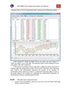
STEP1: Open 【gain adjustment】 interface in PANATERM software. Open
【real time automatic adjustment】 function of target axis, to automatically estimate
inertia ratio.
STEP2: Rigidity is set as conservative value. For example, it can be set as level
13 first. Then click to move this high-speed axis with CypCut software. Observe
whether axis is with abnormal sound and vibration, etc. Raise rigidity slowly. When
the axis is with abnormal sound or vibration, level 1~2 should be declined to
guarantee system stability. The final level should not be level 10 and more than level
20. If it’s dual-drive shaft, it starts moving only after modify two pairs of drive shaft
parameters.
STEP3: After rigidity of X axis and Y axis is tested, set rigidity level as the same
level to guarantee response of two axes are the same. The smaller rigidity is standard.
For example, X axis is level 19 and Y axis is level 16. Finally, set X axis and Y axis
as level 16.
STEP4: Close 【real time automatic adjustment】 and save parameters.
5.2.3 Yaskawa servo gain adjustment
Yaskawa servo debugging is similar with the Panasonic. However, there is some
difference. The difference is as below:
SigmaWin+ cannot be used to dual-drive axle ratio estimation, and advanced
auto-tuning. Inertia ratio calculation tool, Servo Tool can be downloaded from
the official website of Friendess to roughly calculate the inertia ratio for each
axis. Advanced users may also accurately calculate the inertia ratio, based on a
change of acceleration torque and acceleration time, by themselves.
We suggest closing Pn140 model tracking function.
We suggest closing Pn170 free adjustment function.
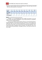
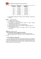
Yaskawa servo does not introduce rigidity and can set the following parameters
based on Panasonic servo rigidity:
Pn102
Pn100
position loop gain: Correspond
speed loop gain: Correspond to
to pr100
pr101 of
oPfaPnaasnoansoicn.ic.
Pn101 speed loop integral time constant: Correspond
Pn401 Torque filter time constant: Correspond to
to pr102
pr104 of
PofanPaasnoansiocn. ic.
The table is as below, and you should pay attention to unit and decimal point.
The unit of Yaskawa speed loop integral time constant, Pn101, is 0101 ms,
while the one of Panasonic is 0.1 millisecond.

