FSCUT2000C laser cutting control system User Manual
16
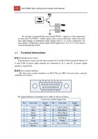
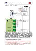
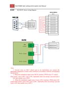
+24V,0V: Supply 24V DC power for servo drive; SON:
The output is servo enable signal when servo on; ALM:
Alarm, receive servo alarm signal;
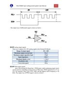
PUL+, PUL-: Pulse (PULS), differential output signal;
DIR+,DIR-: Direction (DIR), differential output signal;
A+, A-, B+, B-, Z+, Z-: Three phase of encoder, input signal;
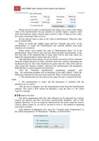
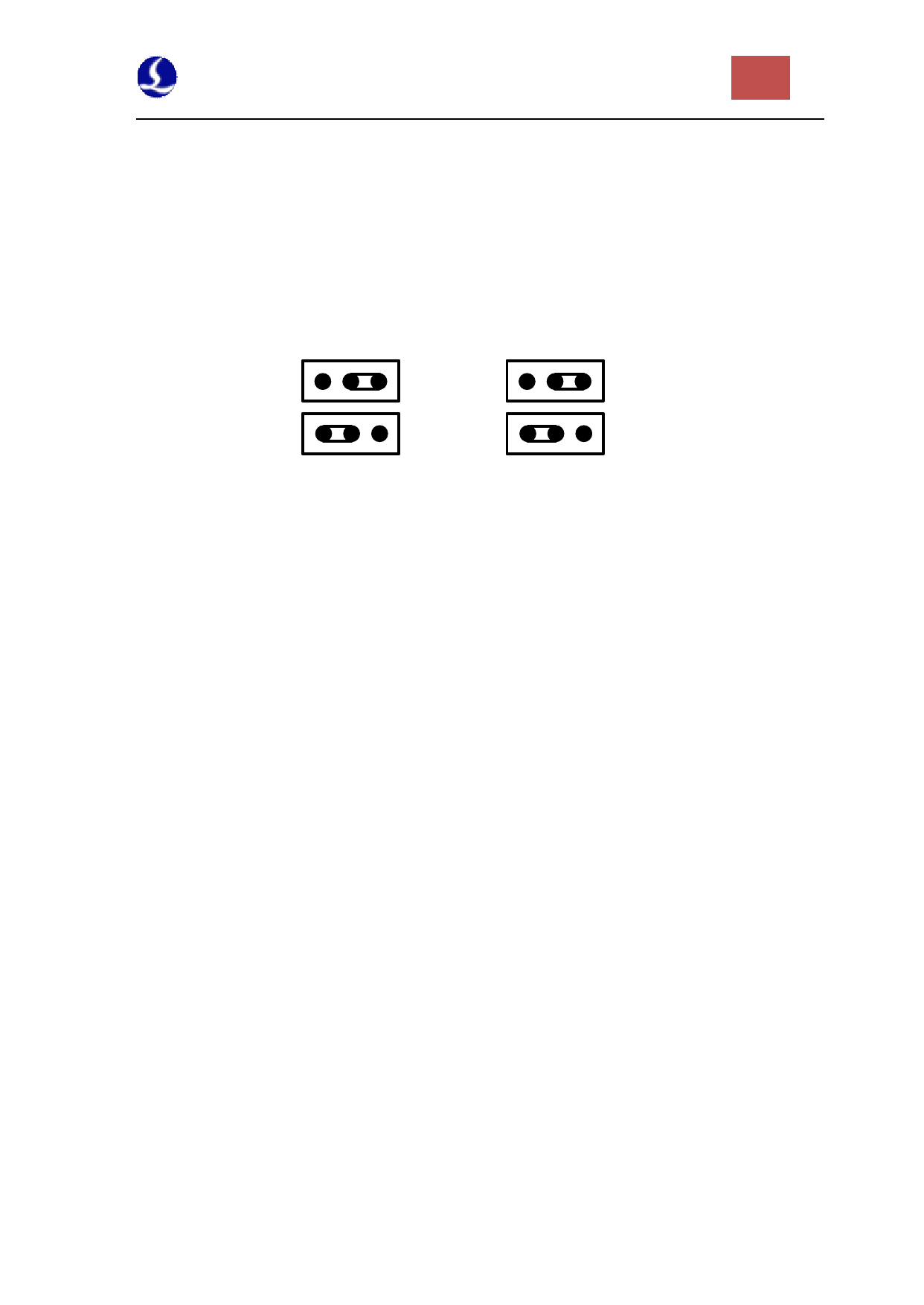
The polarity of SON and ALM signal can be modified through hardware jumper.
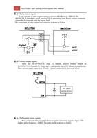
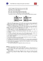
SON
ACT_LOW
ALM
ACT_LOW
ACT_HIGH
ACT_HIGH
When the SON signal jump to ACT_LOW state, low level is active (inputting 0V
voltage is active); When the SON signal jump to ACT_HIGH state, high level is active
(inputting 24V voltage is active). Default state is ACT_LOW.
When the ALM signal jump to ACT_LOW state, low level is active (inputting 0V
voltage is active); When the ALM signal jump to ACT_HIGH state, high level is active
(inputting 24V voltage is active). Default state is ACT_LOW.
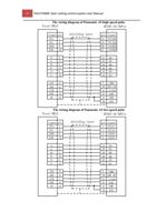
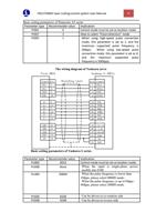
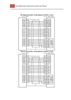
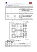
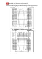
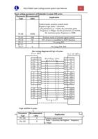
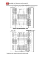
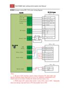
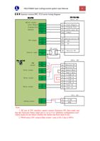
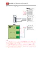
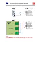
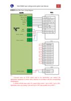
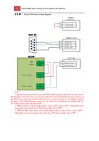
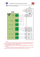
Please refer to “1.3.3 The wiring diagram of servo drive control signal” for
connection of Panasonic, Yaskawa, Mitsubishi and Delta servo drivers.
Please pay attention to the following information when connect servo driver of
other brands:
(1) Please confirm the type of servo driver SON signal you select whether low
level is active or not. (That is, It is ON when connecting with 24V GND.)
(2) Confirm the parameters of servo driver are set as: the type of received pulse
signal is “pulse + direction”
(3) Confirm whether t h e servo driver input terminal has external crash stopping
signal input or not, and which logic the signal is.
(4) Before the trial operation of servo driver, 24 V power must be provided for
External IO Board, for 24 V power servo driver needs is provided by External IO Board.
(5) If driver still cannot run, confirm that driver parameter is set as not using
“positive & negative input inhibit”.
(6) Connect shielding layer of signal line with servo driver case.
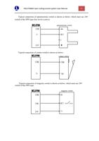
2.3.3 The wiring diagram of servo drive control signal
FSCUT2000 motion control system apply the signal of “Pulse+Direction” to
control servo driver. The pulse sending frequency cap is increased from the previous
750Kpps to 3Mpps.
Recommend using high-speed differential pulse signal, and setting the pulse
equivalent of servo driver in 1000 ~2000, in order to improve the interpolation
accuracy.

