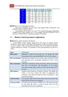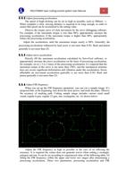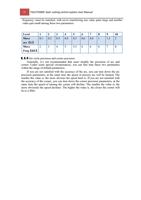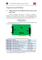
11 FSCUT2000C laser cutting control system User Manual
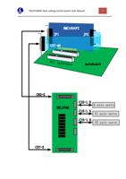
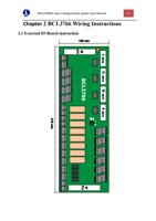
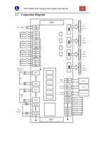
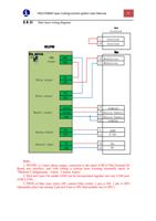
The External IO Board of BCL3766 is installed by rail and also can be installed
permanently. Its external size is 315mm*128mm with DM62M and DB37M interface
in two sides, corresponding to JP1 and JP2 of BMC1604V2. C62-2 cable is used to
connect External IO Board DB62 interface with JP1 port on the back of control card
JP2 interface is linked by C37-40 baffle wire and then is fixed on erection fixture of
computer with bolts. And C37-2 cable is used to connect DB37 socket on External IO
Board.
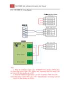
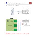
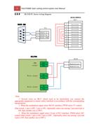
The four DB15M interfaces on the top left corner are servo control signals, which
are X axis, Y axis and W axis, respectively, from left to right. When being used as
gantry dual drive, W axis is as Y2 axis. When being used as pipe cutting, W axis is as
rotation axis.
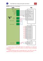
High-low terminals on bottom left are respectively limit and origin signal of X axis
and Y axis. High-low terminals on upper right are origin and limit input of W axis and
general input interface, with all the low terminals break-over, as COM ground, namely 0
V.
The interface on bottom right is 20 general outputs, thereto, 8 outputs as relay
output, 12 outputs as mosfet output. The first 4 ones of the 8 relay outputs only have
normally open contacts and the second 4 outputs have normally open contacts and the
second 4 outputs have normally open contacts and normally closed contacts. The 8th
mosfet output is 24 V general cathode output.
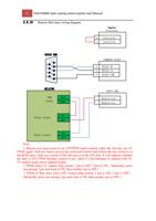
The three 2--pin terminals over right above are 1 PWM and 2 DA analog signal.
Dip switch:
There is a 4-bit dip switch below the PWM and DA analog signal. Its usage is
shown as below :
The first bit (P1) and second bit (P2) of 4-bit dip switch choose PWM voltage.
P1
P2
Implication
On
Off
PWM voltage is 24V
Off
On
PWM voltage is 5V
2.2 Signal type
2.2.1 Input signals
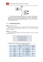
Input signals include: limit, origin and general input. The input of BMC1604 V2
card is active low level: support normally open and normally closed mode (The
polarity of input port can be modified by “platform configuration tool” of CypCut
software). When the setting is normally open, input port and 0 V break-over are active;
when the setting is normally closed, disconnection of 0 V is active.
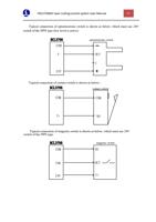
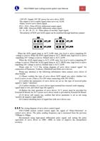
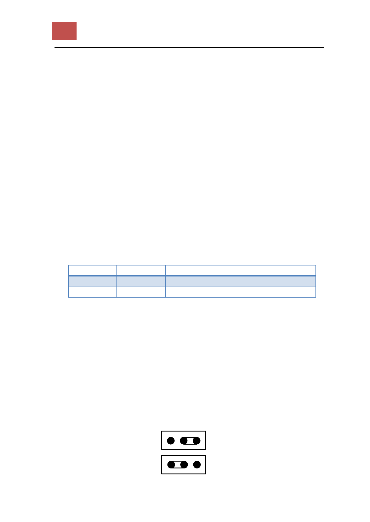
Input port polarity can be modified through the hardware jumper. Now IN13,
IN14 and IN15 input ports support this function. Jumper has two states, ACT_LOW as
shown in the figure, which means low level is active (inputting 0V voltage is active);
ACT_HIGH as shown in the figure, which means high level is active (inputting 24V
voltage is active). Default state is ACT_LOW.
ACT_LOW
ACT_HIGH

