MEASURE & SCALE
MANAGE PARTS
Having a system to identify individual parts
greatly simplifies the process of making a large
project. Labeling parts in the digital file and
physically marking them as they come off the
machine helps you keep track as you move
through the digital workflow and into fabrica-
tion, finishing, and assembly. Labeling allows
you to handle parts methodically and consis-
tently, and it also keeps you from overlooking
or losing a part. Beyond just keeping track,
marking the screen’s numerous similar parts
also streamlines the process of putting it
together.
When you open AtFAB_SCR.skp, you’ll find
seven sheets laid out with part numbers loca-
ted on each part. You can manually mark the
cut parts with these numbers by applying
removable adhesive labels, just before the parts
are removed from the CNC machine bed. Alter-
natively, you can draw discrete part numbers in
CAD and program a toolpath to etch a number
directly into each part.
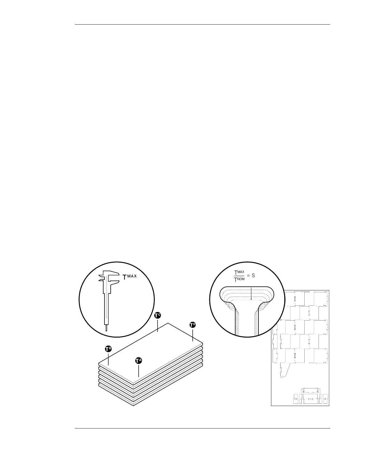
MEASURE & SCALE
01: Once you have your 1/2″ thick sheet mate-
rial in the shop, review “Measure Your Materi-
als” on page 132. Thoroughly measure each of
the seven sheets to get TA, TB, TC, TD, as illus-
trated in Figure 16-2.
02: Record these measurements for each sheet
and calculate TMAX, your actual material thick-
ness. While measuring 28 times seems abso-
lutely tedious, the extra effort allows you to
find any dimensional variation that might
cause trouble for your joinery later on.
03: Once you’ve identified TMAX, refer to “Scale
Your CAD File” on page 133 on how to divide
TMAX by TNOM to define your file-scaling per-
centage (S). The TNOM for the Cellular Screen
is ½″ (12mm).
FIGURE 16-2
How to measure and
scale the Cellular
Screen file
310
DESIGN FOR CNC

 Design for CNC, Furniture Projects and Fabrication Technique")
 Design for CNC, Furniture Projects and Fabrication Technique")
 Design for CNC, Furniture Projects and Fabrication Technique")
 Design for CNC, Furniture Projects and Fabrication Technique")
 Design for CNC, Furniture Projects and Fabrication Technique")
 Design for CNC, Furniture Projects and Fabrication Technique")
 Design for CNC, Furniture Projects and Fabrication Technique")
 Design for CNC, Furniture Projects and Fabrication Technique")
 Design for CNC, Furniture Projects and Fabrication Technique")
 Design for CNC, Furniture Projects and Fabrication Technique")
 Design for CNC, Furniture Projects and Fabrication Technique")
 Design for CNC, Furniture Projects and Fabrication Technique")
 Design for CNC, Furniture Projects and Fabrication Technique")
 Design for CNC, Furniture Projects and Fabrication Technique")
 Design for CNC, Furniture Projects and Fabrication Technique")
 Design for CNC, Furniture Projects and Fabrication Technique")
 Design for CNC, Furniture Projects and Fabrication Technique")
 Design for CNC, Furniture Projects and Fabrication Technique")
 Design for CNC, Furniture Projects and Fabrication Technique")
 Design for CNC, Furniture Projects and Fabrication Technique")
 Design for CNC, Furniture Projects and Fabrication Technique")
 Design for CNC, Furniture Projects and Fabrication Technique")
 Design for CNC, Furniture Projects and Fabrication Technique")
 Design for CNC, Furniture Projects and Fabrication Technique")
 Design for CNC, Furniture Projects and Fabrication Technique")
 Design for CNC, Furniture Projects and Fabrication Technique")
 Design for CNC, Furniture Projects and Fabrication Technique")
 Design for CNC, Furniture Projects and Fabrication Technique")
 Design for CNC, Furniture Projects and Fabrication Technique")
 Design for CNC, Furniture Projects and Fabrication Technique")
 Design for CNC, Furniture Projects and Fabrication Technique")
 Design for CNC, Furniture Projects and Fabrication Technique")
 Design for CNC, Furniture Projects and Fabrication Technique")
 Design for CNC, Furniture Projects and Fabrication Technique")
 Design for CNC, Furniture Projects and Fabrication Technique")
 Design for CNC, Furniture Projects and Fabrication Technique")
 Design for CNC, Furniture Projects and Fabrication Technique")
 Design for CNC, Furniture Projects and Fabrication Technique")
 Design for CNC, Furniture Projects and Fabrication Technique")
 Design for CNC, Furniture Projects and Fabrication Technique")
 Design for CNC, Furniture Projects and Fabrication Technique")
 Design for CNC, Furniture Projects and Fabrication Technique")
 Design for CNC, Furniture Projects and Fabrication Technique")
 Design for CNC, Furniture Projects and Fabrication Technique")
 Design for CNC, Furniture Projects and Fabrication Technique")
 Design for CNC, Furniture Projects and Fabrication Technique")
 Design for CNC, Furniture Projects and Fabrication Technique")
 Design for CNC, Furniture Projects and Fabrication Technique")
 Design for CNC, Furniture Projects and Fabrication Technique")
 Design for CNC, Furniture Projects and Fabrication Technique")
 Design for CNC, Furniture Projects and Fabrication Technique")
 Design for CNC, Furniture Projects and Fabrication Technique")
 Design for CNC, Furniture Projects and Fabrication Technique")
 Design for CNC, Furniture Projects and Fabrication Technique")
 Design for CNC, Furniture Projects and Fabrication Technique")
 Design for CNC, Furniture Projects and Fabrication Technique")
 Design for CNC, Furniture Projects and Fabrication Technique")
 Design for CNC, Furniture Projects and Fabrication Technique")
 Design for CNC, Furniture Projects and Fabrication Technique")
 Design for CNC, Furniture Projects and Fabrication Technique")
 Design for CNC, Furniture Projects and Fabrication Technique")
 Design for CNC, Furniture Projects and Fabrication Technique")
 Design for CNC, Furniture Projects and Fabrication Technique")
 Design for CNC, Furniture Projects and Fabrication Technique")
 Design for CNC, Furniture Projects and Fabrication Technique")
 Design for CNC, Furniture Projects and Fabrication Technique")
 Design for CNC, Furniture Projects and Fabrication Technique")
 Design for CNC, Furniture Projects and Fabrication Technique")
 Design for CNC, Furniture Projects and Fabrication Technique")
 Design for CNC, Furniture Projects and Fabrication Technique")
 Design for CNC, Furniture Projects and Fabrication Technique")
 Design for CNC, Furniture Projects and Fabrication Technique")
 Design for CNC, Furniture Projects and Fabrication Technique")
 Design for CNC, Furniture Projects and Fabrication Technique")
 Design for CNC, Furniture Projects and Fabrication Technique")
 Design for CNC, Furniture Projects and Fabrication Technique")
 Design for CNC, Furniture Projects and Fabrication Technique")
 Design for CNC, Furniture Projects and Fabrication Technique")
 Design for CNC, Furniture Projects and Fabrication Technique")
 Design for CNC, Furniture Projects and Fabrication Technique")
 Design for CNC, Furniture Projects and Fabrication Technique")
 Design for CNC, Furniture Projects and Fabrication Technique")
 Design for CNC, Furniture Projects and Fabrication Technique")
 Design for CNC, Furniture Projects and Fabrication Technique")
 Design for CNC, Furniture Projects and Fabrication Technique")
 Design for CNC, Furniture Projects and Fabrication Technique")
 Design for CNC, Furniture Projects and Fabrication Technique")
 Design for CNC, Furniture Projects and Fabrication Technique")
 Design for CNC, Furniture Projects and Fabrication Technique")
 Design for CNC, Furniture Projects and Fabrication Technique")
 Design for CNC, Furniture Projects and Fabrication Technique")
 Design for CNC, Furniture Projects and Fabrication Technique")
 Design for CNC, Furniture Projects and Fabrication Technique")
 Design for CNC, Furniture Projects and Fabrication Technique")
 Design for CNC, Furniture Projects and Fabrication Technique")