OUTSIDE PROFILE TOOLPATHS
OUTSIDE PROFILE TOOLPATHS
Now it’s time to cut out the parts by creating
outside profiles. You’ll repeat the same process
of selecting vectors and then programming the
toolpaths like you did previously with the inside
seat toolpaths, using the same ¼″ end mill.
TURN ON LAYER, SELECT VECTORS
29A: Return to the main VCarve window and
turn on the Profile Outside layer, 000 AtFAB
stools_profile outside.
29B: Select the vectors.
SELECT ¼″ TOOL
30A: Create a new outside profile toolpath by
keeping the vectors selected and then clicking
the profile toolpath icon under the Toolpaths
menu→2D Profile Toolpath.
30B: Open the Toolpath Database by pressing
the Select… button under the Tool section,
Toolpaths menu→2D Profile Toolpath→Tool.
30C: Select a 0.25 inch end mill (¼″), Tool
List→Imperial Tools→End Mill (0.25 inch).
CREATE OUTSIDE PROFILES
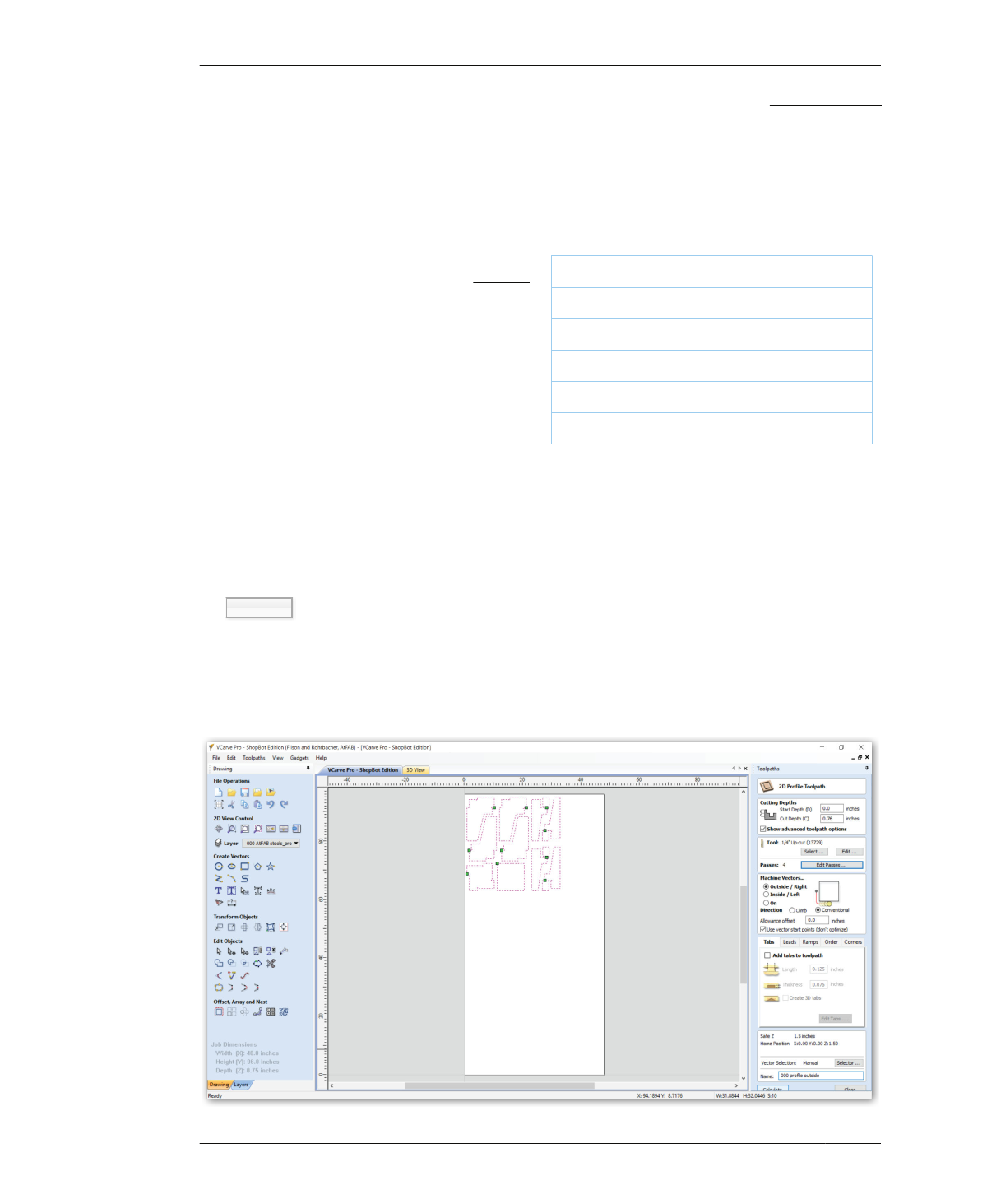
31A: Enter the settings shown in Table 7-2.
Any settings not specified will be left as the
VCarve Tool Database default.
TABLE 7-2. Outside Profile Settings
Tool Diameter
0.25 inch (¼″) end mill
Passes
3
Cut Depth
0.76”
Machine Vectors
Outside/Right
Direction
Conventional
Toolpath Name
000 Outside Profiles
SIMULATE OUTSIDE PROFILES
VCarve automatically adds this third toolpath
(000 Outside Profiles) to the Toolpath List at
the bottom of the right-hand Toolpaths menu.
As before, review the animation and visuals of
the vectors, spindle path, as well as the actual
cuts made by the ¼″ end mill. Ensure that kerf
matches the end-mill size, that material is cut
all the way through, and that the cut shapes
match those in the original cut file.
FIGURE 7-40
Isolate Outside Profiles
192
DESIGN FOR CNC

 Design for CNC, Furniture Projects and Fabrication Technique")
 Design for CNC, Furniture Projects and Fabrication Technique")
 Design for CNC, Furniture Projects and Fabrication Technique")
 Design for CNC, Furniture Projects and Fabrication Technique")
 Design for CNC, Furniture Projects and Fabrication Technique")
 Design for CNC, Furniture Projects and Fabrication Technique")
 Design for CNC, Furniture Projects and Fabrication Technique")
 Design for CNC, Furniture Projects and Fabrication Technique")
 Design for CNC, Furniture Projects and Fabrication Technique")
 Design for CNC, Furniture Projects and Fabrication Technique")
 Design for CNC, Furniture Projects and Fabrication Technique")
 Design for CNC, Furniture Projects and Fabrication Technique")
 Design for CNC, Furniture Projects and Fabrication Technique")
 Design for CNC, Furniture Projects and Fabrication Technique")
 Design for CNC, Furniture Projects and Fabrication Technique")
 Design for CNC, Furniture Projects and Fabrication Technique")
 Design for CNC, Furniture Projects and Fabrication Technique")
 Design for CNC, Furniture Projects and Fabrication Technique")
 Design for CNC, Furniture Projects and Fabrication Technique")
 Design for CNC, Furniture Projects and Fabrication Technique")
 Design for CNC, Furniture Projects and Fabrication Technique")
 Design for CNC, Furniture Projects and Fabrication Technique")
 Design for CNC, Furniture Projects and Fabrication Technique")
 Design for CNC, Furniture Projects and Fabrication Technique")
 Design for CNC, Furniture Projects and Fabrication Technique")
 Design for CNC, Furniture Projects and Fabrication Technique")
 Design for CNC, Furniture Projects and Fabrication Technique")
 Design for CNC, Furniture Projects and Fabrication Technique")
 Design for CNC, Furniture Projects and Fabrication Technique")
 Design for CNC, Furniture Projects and Fabrication Technique")
 Design for CNC, Furniture Projects and Fabrication Technique")
 Design for CNC, Furniture Projects and Fabrication Technique")
 Design for CNC, Furniture Projects and Fabrication Technique")
 Design for CNC, Furniture Projects and Fabrication Technique")
 Design for CNC, Furniture Projects and Fabrication Technique")
 Design for CNC, Furniture Projects and Fabrication Technique")
 Design for CNC, Furniture Projects and Fabrication Technique")
 Design for CNC, Furniture Projects and Fabrication Technique")
 Design for CNC, Furniture Projects and Fabrication Technique")
 Design for CNC, Furniture Projects and Fabrication Technique")
 Design for CNC, Furniture Projects and Fabrication Technique")
 Design for CNC, Furniture Projects and Fabrication Technique")
 Design for CNC, Furniture Projects and Fabrication Technique")
 Design for CNC, Furniture Projects and Fabrication Technique")
 Design for CNC, Furniture Projects and Fabrication Technique")
 Design for CNC, Furniture Projects and Fabrication Technique")
 Design for CNC, Furniture Projects and Fabrication Technique")
 Design for CNC, Furniture Projects and Fabrication Technique")
 Design for CNC, Furniture Projects and Fabrication Technique")
 Design for CNC, Furniture Projects and Fabrication Technique")
 Design for CNC, Furniture Projects and Fabrication Technique")
 Design for CNC, Furniture Projects and Fabrication Technique")
 Design for CNC, Furniture Projects and Fabrication Technique")
 Design for CNC, Furniture Projects and Fabrication Technique")
 Design for CNC, Furniture Projects and Fabrication Technique")
 Design for CNC, Furniture Projects and Fabrication Technique")
 Design for CNC, Furniture Projects and Fabrication Technique")
 Design for CNC, Furniture Projects and Fabrication Technique")
 Design for CNC, Furniture Projects and Fabrication Technique")
 Design for CNC, Furniture Projects and Fabrication Technique")
 Design for CNC, Furniture Projects and Fabrication Technique")
 Design for CNC, Furniture Projects and Fabrication Technique")
 Design for CNC, Furniture Projects and Fabrication Technique")
 Design for CNC, Furniture Projects and Fabrication Technique")
 Design for CNC, Furniture Projects and Fabrication Technique")
 Design for CNC, Furniture Projects and Fabrication Technique")
 Design for CNC, Furniture Projects and Fabrication Technique")
 Design for CNC, Furniture Projects and Fabrication Technique")
 Design for CNC, Furniture Projects and Fabrication Technique")
 Design for CNC, Furniture Projects and Fabrication Technique")
 Design for CNC, Furniture Projects and Fabrication Technique")
 Design for CNC, Furniture Projects and Fabrication Technique")
 Design for CNC, Furniture Projects and Fabrication Technique")
 Design for CNC, Furniture Projects and Fabrication Technique")
 Design for CNC, Furniture Projects and Fabrication Technique")
 Design for CNC, Furniture Projects and Fabrication Technique")
 Design for CNC, Furniture Projects and Fabrication Technique")
 Design for CNC, Furniture Projects and Fabrication Technique")
 Design for CNC, Furniture Projects and Fabrication Technique")
 Design for CNC, Furniture Projects and Fabrication Technique")
 Design for CNC, Furniture Projects and Fabrication Technique")
 Design for CNC, Furniture Projects and Fabrication Technique")
 Design for CNC, Furniture Projects and Fabrication Technique")
 Design for CNC, Furniture Projects and Fabrication Technique")
 Design for CNC, Furniture Projects and Fabrication Technique")
 Design for CNC, Furniture Projects and Fabrication Technique")
 Design for CNC, Furniture Projects and Fabrication Technique")
 Design for CNC, Furniture Projects and Fabrication Technique")
 Design for CNC, Furniture Projects and Fabrication Technique")
 Design for CNC, Furniture Projects and Fabrication Technique")
 Design for CNC, Furniture Projects and Fabrication Technique")
 Design for CNC, Furniture Projects and Fabrication Technique")
 Design for CNC, Furniture Projects and Fabrication Technique")
 Design for CNC, Furniture Projects and Fabrication Technique")
 Design for CNC, Furniture Projects and Fabrication Technique")