FASTENER HOLE TOOLPATHS
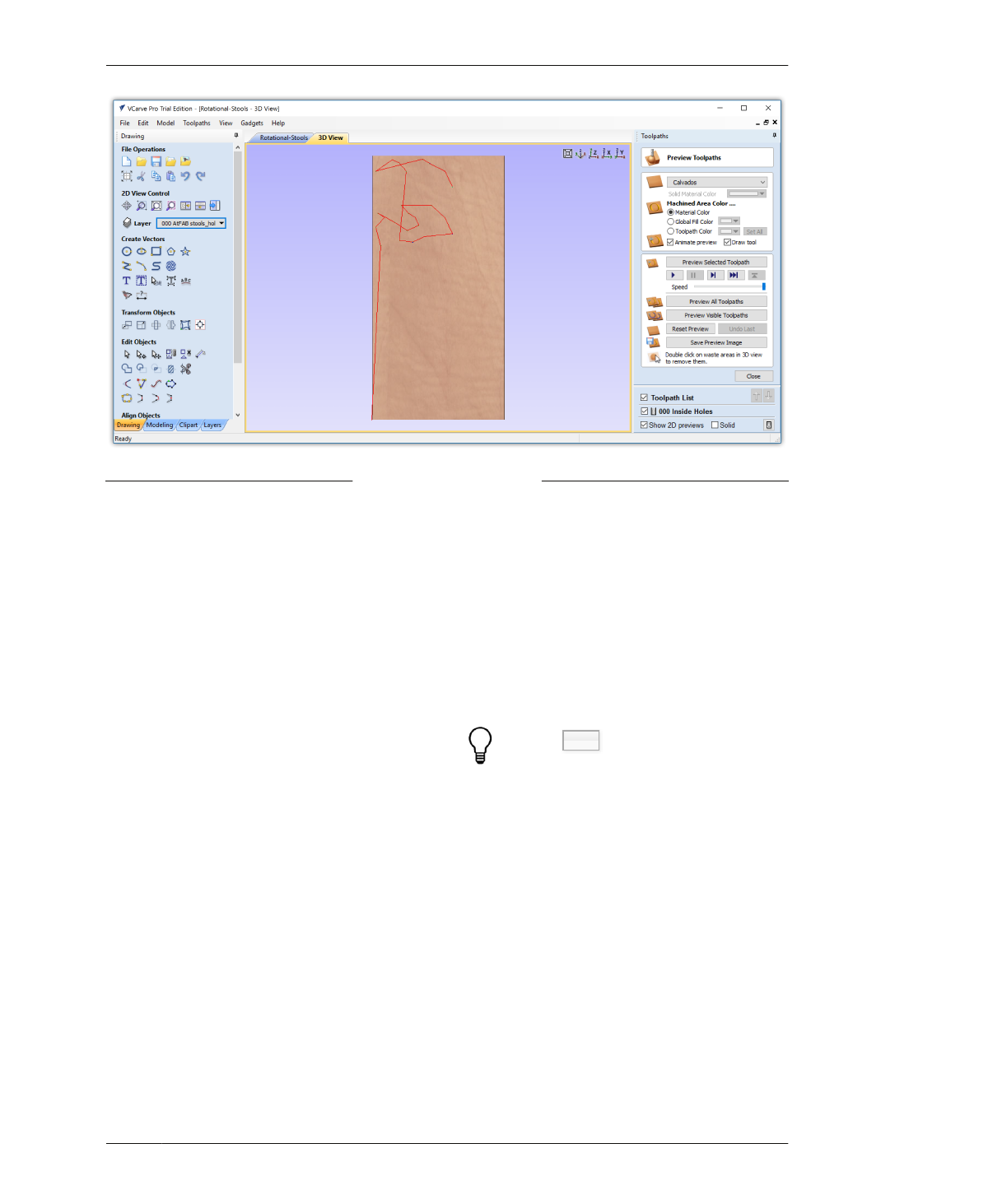
FIGURE 7-34
Profile toolpath created
and 3D machining sim-
ulation shown
SIMULATE TOOLPATHS
After it calculates your toolpath definition,
VCarve automatically opens the 3D Window
and Preview Tab, as shown in Figure 7-34.
Besides allowing you to pan, zoom, and rotate
the view of your sheet material, VCarve simu-
lates your toolpath definitions through anima-
tion and visuals.
By visually showing the toolpath, or actual
movements that the end-mill will make, you’ll
be able to analyze the results and make any
necessary corrections.
25A: Zoom in and take a look around. The red
lines are the X and Y, or horizontal, moves that
the tool will make. The green lines are the verti-
cal moves. The blue holes are the individual
passes at different three-dimensional depths.
25B: Click the tab above the visualization
next to “3D View” that says “Rotational Stools”
to flip back to the CAD file vector view, as
shown in Figure 7-36. As demonstrated in “Cre-
ating Profile Toolpaths From Vectors” on page
180, this view shows the part vectors in red and
the toolpath in pink with little arrows indicating
the direction the tool will travel as it cuts.
Hold the Ctrl key to pan. Zoom in and out or
orbit by scrolling with the mouse.
07/MODELING SOFTWARE TO MACHINE
187

 Design for CNC, Furniture Projects and Fabrication Technique")
 Design for CNC, Furniture Projects and Fabrication Technique")
 Design for CNC, Furniture Projects and Fabrication Technique")
 Design for CNC, Furniture Projects and Fabrication Technique")
 Design for CNC, Furniture Projects and Fabrication Technique")
 Design for CNC, Furniture Projects and Fabrication Technique")
 Design for CNC, Furniture Projects and Fabrication Technique")
 Design for CNC, Furniture Projects and Fabrication Technique")
 Design for CNC, Furniture Projects and Fabrication Technique")
 Design for CNC, Furniture Projects and Fabrication Technique")
 Design for CNC, Furniture Projects and Fabrication Technique")
 Design for CNC, Furniture Projects and Fabrication Technique")
 Design for CNC, Furniture Projects and Fabrication Technique")
 Design for CNC, Furniture Projects and Fabrication Technique")
 Design for CNC, Furniture Projects and Fabrication Technique")
 Design for CNC, Furniture Projects and Fabrication Technique")
 Design for CNC, Furniture Projects and Fabrication Technique")
 Design for CNC, Furniture Projects and Fabrication Technique")
 Design for CNC, Furniture Projects and Fabrication Technique")
 Design for CNC, Furniture Projects and Fabrication Technique")
 Design for CNC, Furniture Projects and Fabrication Technique")
 Design for CNC, Furniture Projects and Fabrication Technique")
 Design for CNC, Furniture Projects and Fabrication Technique")
 Design for CNC, Furniture Projects and Fabrication Technique")
 Design for CNC, Furniture Projects and Fabrication Technique")
 Design for CNC, Furniture Projects and Fabrication Technique")
 Design for CNC, Furniture Projects and Fabrication Technique")
 Design for CNC, Furniture Projects and Fabrication Technique")
 Design for CNC, Furniture Projects and Fabrication Technique")
 Design for CNC, Furniture Projects and Fabrication Technique")
 Design for CNC, Furniture Projects and Fabrication Technique")
 Design for CNC, Furniture Projects and Fabrication Technique")
 Design for CNC, Furniture Projects and Fabrication Technique")
 Design for CNC, Furniture Projects and Fabrication Technique")
 Design for CNC, Furniture Projects and Fabrication Technique")
 Design for CNC, Furniture Projects and Fabrication Technique")
 Design for CNC, Furniture Projects and Fabrication Technique")
 Design for CNC, Furniture Projects and Fabrication Technique")
 Design for CNC, Furniture Projects and Fabrication Technique")
 Design for CNC, Furniture Projects and Fabrication Technique")
 Design for CNC, Furniture Projects and Fabrication Technique")
 Design for CNC, Furniture Projects and Fabrication Technique")
 Design for CNC, Furniture Projects and Fabrication Technique")
 Design for CNC, Furniture Projects and Fabrication Technique")
 Design for CNC, Furniture Projects and Fabrication Technique")
 Design for CNC, Furniture Projects and Fabrication Technique")
 Design for CNC, Furniture Projects and Fabrication Technique")
 Design for CNC, Furniture Projects and Fabrication Technique")
 Design for CNC, Furniture Projects and Fabrication Technique")
 Design for CNC, Furniture Projects and Fabrication Technique")
 Design for CNC, Furniture Projects and Fabrication Technique")
 Design for CNC, Furniture Projects and Fabrication Technique")
 Design for CNC, Furniture Projects and Fabrication Technique")
 Design for CNC, Furniture Projects and Fabrication Technique")
 Design for CNC, Furniture Projects and Fabrication Technique")
 Design for CNC, Furniture Projects and Fabrication Technique")
 Design for CNC, Furniture Projects and Fabrication Technique")
 Design for CNC, Furniture Projects and Fabrication Technique")
 Design for CNC, Furniture Projects and Fabrication Technique")
 Design for CNC, Furniture Projects and Fabrication Technique")
 Design for CNC, Furniture Projects and Fabrication Technique")
 Design for CNC, Furniture Projects and Fabrication Technique")
 Design for CNC, Furniture Projects and Fabrication Technique")
 Design for CNC, Furniture Projects and Fabrication Technique")
 Design for CNC, Furniture Projects and Fabrication Technique")
 Design for CNC, Furniture Projects and Fabrication Technique")
 Design for CNC, Furniture Projects and Fabrication Technique")
 Design for CNC, Furniture Projects and Fabrication Technique")
 Design for CNC, Furniture Projects and Fabrication Technique")
 Design for CNC, Furniture Projects and Fabrication Technique")
 Design for CNC, Furniture Projects and Fabrication Technique")
 Design for CNC, Furniture Projects and Fabrication Technique")
 Design for CNC, Furniture Projects and Fabrication Technique")
 Design for CNC, Furniture Projects and Fabrication Technique")
 Design for CNC, Furniture Projects and Fabrication Technique")
 Design for CNC, Furniture Projects and Fabrication Technique")
 Design for CNC, Furniture Projects and Fabrication Technique")
 Design for CNC, Furniture Projects and Fabrication Technique")
 Design for CNC, Furniture Projects and Fabrication Technique")
 Design for CNC, Furniture Projects and Fabrication Technique")
 Design for CNC, Furniture Projects and Fabrication Technique")
 Design for CNC, Furniture Projects and Fabrication Technique")
 Design for CNC, Furniture Projects and Fabrication Technique")
 Design for CNC, Furniture Projects and Fabrication Technique")
 Design for CNC, Furniture Projects and Fabrication Technique")
 Design for CNC, Furniture Projects and Fabrication Technique")
 Design for CNC, Furniture Projects and Fabrication Technique")
 Design for CNC, Furniture Projects and Fabrication Technique")
 Design for CNC, Furniture Projects and Fabrication Technique")
 Design for CNC, Furniture Projects and Fabrication Technique")
 Design for CNC, Furniture Projects and Fabrication Technique")
 Design for CNC, Furniture Projects and Fabrication Technique")
 Design for CNC, Furniture Projects and Fabrication Technique")
 Design for CNC, Furniture Projects and Fabrication Technique")
 Design for CNC, Furniture Projects and Fabrication Technique")