SNIGLETS AND FASTENERS
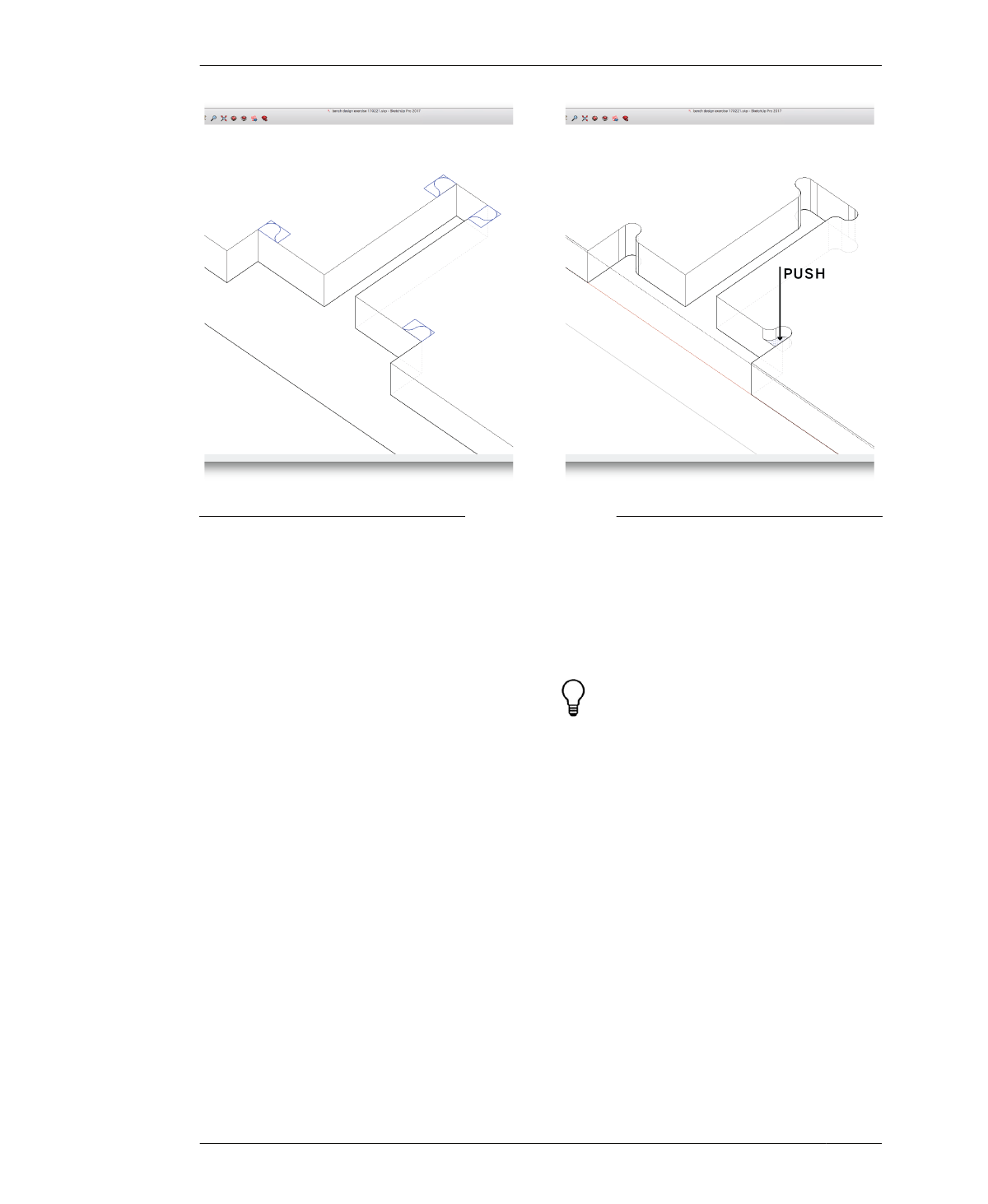
FIGURE 4-30
Locate sniglet profiles
and then form into 3D
MODEL SNIGLETS
Sniglets go into every interior corner, to elimi-
nate corner material and to accommodate
flush-fitting joinery. While some CAM programs
(like VCarve Pro) have utilities you can use to
add dogbone or T-bone fillets to your design,
this extra step allows you a bit more control.
You can pay more attention to the actual corner
detail profile, while also thoroughly considering
its exact direction and placement in the overall
design.
24A: Working on a 2D flattened part, place a
sniglet at every inside corner. Be sure to work
outside the component itself as you place and
arrange sniglets.
24B: Select the collection of sniglet compo-
nents and go to Edit→Cut.
24C: Select and Edit the part component.
Edit→Paste the sniglet collection and explode
the individual sniglet components.
24D: Using the Push/Pull tool, push the snig-
let shape into and through the part.
24E: Exit the part component and repeat until
all parts have sniglets on every inside corner.
It’s usually more convenient to work on the 2D
parts as you introduce sniglets and holes,
especially in those cases where access to the
part is limited. When you want to work on
parts configured in 3D, it’s helpful to use
transparency view options as much as possi-
ble, so you can clearly understand parts. It
can also help to isolate or temporarily move
components in 3D to work on them.
120
DESIGN FOR CNC

 Design for CNC, Furniture Projects and Fabrication Technique")
 Design for CNC, Furniture Projects and Fabrication Technique")
 Design for CNC, Furniture Projects and Fabrication Technique")
 Design for CNC, Furniture Projects and Fabrication Technique")
 Design for CNC, Furniture Projects and Fabrication Technique")
 Design for CNC, Furniture Projects and Fabrication Technique")
 Design for CNC, Furniture Projects and Fabrication Technique")
 Design for CNC, Furniture Projects and Fabrication Technique")
 Design for CNC, Furniture Projects and Fabrication Technique")
 Design for CNC, Furniture Projects and Fabrication Technique")
 Design for CNC, Furniture Projects and Fabrication Technique")
 Design for CNC, Furniture Projects and Fabrication Technique")
 Design for CNC, Furniture Projects and Fabrication Technique")
 Design for CNC, Furniture Projects and Fabrication Technique")
 Design for CNC, Furniture Projects and Fabrication Technique")
 Design for CNC, Furniture Projects and Fabrication Technique")
 Design for CNC, Furniture Projects and Fabrication Technique")
 Design for CNC, Furniture Projects and Fabrication Technique")
 Design for CNC, Furniture Projects and Fabrication Technique")
 Design for CNC, Furniture Projects and Fabrication Technique")
 Design for CNC, Furniture Projects and Fabrication Technique")
 Design for CNC, Furniture Projects and Fabrication Technique")
 Design for CNC, Furniture Projects and Fabrication Technique")
 Design for CNC, Furniture Projects and Fabrication Technique")
 Design for CNC, Furniture Projects and Fabrication Technique")
 Design for CNC, Furniture Projects and Fabrication Technique")
 Design for CNC, Furniture Projects and Fabrication Technique")
 Design for CNC, Furniture Projects and Fabrication Technique")
 Design for CNC, Furniture Projects and Fabrication Technique")
 Design for CNC, Furniture Projects and Fabrication Technique")
 Design for CNC, Furniture Projects and Fabrication Technique")
 Design for CNC, Furniture Projects and Fabrication Technique")
 Design for CNC, Furniture Projects and Fabrication Technique")
 Design for CNC, Furniture Projects and Fabrication Technique")
 Design for CNC, Furniture Projects and Fabrication Technique")
 Design for CNC, Furniture Projects and Fabrication Technique")
 Design for CNC, Furniture Projects and Fabrication Technique")
 Design for CNC, Furniture Projects and Fabrication Technique")
 Design for CNC, Furniture Projects and Fabrication Technique")
 Design for CNC, Furniture Projects and Fabrication Technique")
 Design for CNC, Furniture Projects and Fabrication Technique")
 Design for CNC, Furniture Projects and Fabrication Technique")
 Design for CNC, Furniture Projects and Fabrication Technique")
 Design for CNC, Furniture Projects and Fabrication Technique")
 Design for CNC, Furniture Projects and Fabrication Technique")
 Design for CNC, Furniture Projects and Fabrication Technique")
 Design for CNC, Furniture Projects and Fabrication Technique")
 Design for CNC, Furniture Projects and Fabrication Technique")
 Design for CNC, Furniture Projects and Fabrication Technique")
 Design for CNC, Furniture Projects and Fabrication Technique")
 Design for CNC, Furniture Projects and Fabrication Technique")
 Design for CNC, Furniture Projects and Fabrication Technique")
 Design for CNC, Furniture Projects and Fabrication Technique")
 Design for CNC, Furniture Projects and Fabrication Technique")
 Design for CNC, Furniture Projects and Fabrication Technique")
 Design for CNC, Furniture Projects and Fabrication Technique")
 Design for CNC, Furniture Projects and Fabrication Technique")
 Design for CNC, Furniture Projects and Fabrication Technique")
 Design for CNC, Furniture Projects and Fabrication Technique")
 Design for CNC, Furniture Projects and Fabrication Technique")
 Design for CNC, Furniture Projects and Fabrication Technique")
 Design for CNC, Furniture Projects and Fabrication Technique")
 Design for CNC, Furniture Projects and Fabrication Technique")
 Design for CNC, Furniture Projects and Fabrication Technique")
 Design for CNC, Furniture Projects and Fabrication Technique")
 Design for CNC, Furniture Projects and Fabrication Technique")
 Design for CNC, Furniture Projects and Fabrication Technique")
 Design for CNC, Furniture Projects and Fabrication Technique")
 Design for CNC, Furniture Projects and Fabrication Technique")
 Design for CNC, Furniture Projects and Fabrication Technique")
 Design for CNC, Furniture Projects and Fabrication Technique")
 Design for CNC, Furniture Projects and Fabrication Technique")
 Design for CNC, Furniture Projects and Fabrication Technique")
 Design for CNC, Furniture Projects and Fabrication Technique")
 Design for CNC, Furniture Projects and Fabrication Technique")
 Design for CNC, Furniture Projects and Fabrication Technique")
 Design for CNC, Furniture Projects and Fabrication Technique")
 Design for CNC, Furniture Projects and Fabrication Technique")
 Design for CNC, Furniture Projects and Fabrication Technique")
 Design for CNC, Furniture Projects and Fabrication Technique")
 Design for CNC, Furniture Projects and Fabrication Technique")
 Design for CNC, Furniture Projects and Fabrication Technique")
 Design for CNC, Furniture Projects and Fabrication Technique")
 Design for CNC, Furniture Projects and Fabrication Technique")
 Design for CNC, Furniture Projects and Fabrication Technique")
 Design for CNC, Furniture Projects and Fabrication Technique")
 Design for CNC, Furniture Projects and Fabrication Technique")
 Design for CNC, Furniture Projects and Fabrication Technique")
 Design for CNC, Furniture Projects and Fabrication Technique")
 Design for CNC, Furniture Projects and Fabrication Technique")
 Design for CNC, Furniture Projects and Fabrication Technique")
 Design for CNC, Furniture Projects and Fabrication Technique")
 Design for CNC, Furniture Projects and Fabrication Technique")
 Design for CNC, Furniture Projects and Fabrication Technique")
 Design for CNC, Furniture Projects and Fabrication Technique")