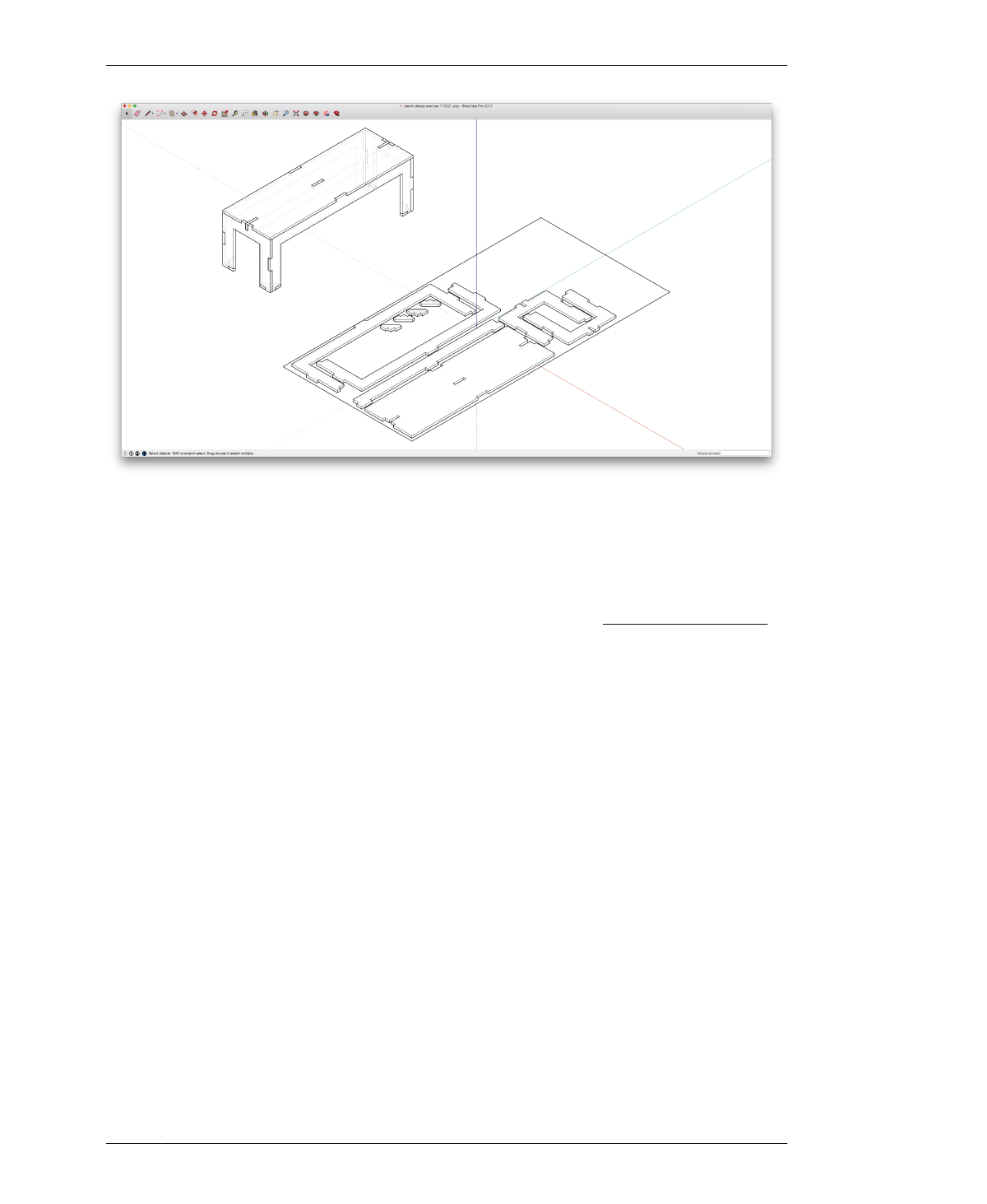
ANALYZE BENCH JOINERY
FIGURE 4-28
Bench with all joinery
ANALYZE BENCH JOINERY
After adding so many small details into the
design, step back, zoom out, and examine the
logic and effects of your joinery. Evaluate
whether the direction, location, and proportion
of all joints support the bench’s hierarchy of
function, as well as its process of assembly.
For instance, part overlaps should accommo-
date seated individuals, who will have the most
contact with the top and front of the bench. In
the design, you’ll see that most of the seat cov-
ers the front edge, with small tabs pushed
toward the center and ends. The seat surface is
continuous where two individuals are most
likely to sit. In addition, joinery adds a nice
detail to the middle of the seat and suggests a
subtle boundary between two seated individu-
als.
Another issue to analyze at this point is con-
structability. It’s entirely possible to design a
piece of furniture in a CAD model that is physi-
cally impossible to assemble in real life. Con-
sider the process of assembly as you design
parts and locate joinery. In the case of the
bench, it’s easy to envision a straightforward
sequence of assembly that forms a frame with
the four sides, places the beam and seat on
top, and the feet on the bottom.
EVALUATE JOINTS
In these next steps, you’ll circle back through
your model and organize the parts to prepare
for the next steps.
21A: Turn on 000_Bench flat to review your 2D
sheet layout parts alongside the parts in their
3D configuration.
21B: Look at the 2D sheet layout and confirm
that there is adequate spacing between com-
ponents, especially after tabs have been intro-
duced.
21C: Check that components in the 3D model
haven’t shifted out of place and also look over
all of your joinery to ensure that tabs align with
slots and faces. If any faces or components are
out of place, modify the component to bring it
or its faces into alignment with adjacent parts.
04/GETTING STARTED WITH DESIGN
117
