MAKE JOINERY
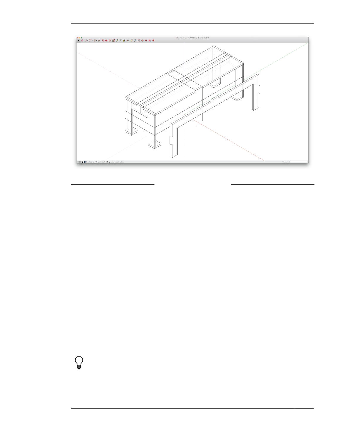
FIGURE 4-21
Front with three new
tabs
MAKE JOINERY ON FRONT
In this section, you’ll form slots and tabs to cre-
ate the end-to-end joints that comprise the cor-
ner assembly, connecting the front, back, and
sides. In these steps, you will apply the same
techniques of drawing construction lines to
help accurately define surfaces that you will
then push/pull into tabs and slots.
17A: Draw construction lines on the top edge
and two side edges of the front component,
using the guidelines as well as the slot you just
modeled on the seat front as a reference.
Select all construction lines and select
Edit→Cut.
17B: Fully select the front component three
mouse clicks are required to select and edit the
component. Edit→Paste the construction lines
into place.
17C: Using the Push/Pull tool, push either
end of the top edge down so that these edges
align with the bottom face of the seat. This
leaves a 4″ × ¾″ × ¾″ tab at the middle that fits
the front seat slot.
17D: Form a tab on the side of leg by using the
Push/Pull tool. Push the surfaces above and
below each side tab, leaving a 4″ × ¾″ × ¾″ tab
centered on the edge of the leg. Repeat on the
other end of the part.
17E: Exit the front component. The front part
should have three tabs, as illustrated in
Figure 4-21. Notice that the back part will auto-
matically update.
Use previously modeled slots and tabs as ref-
erences to assist you in drawing construction
lines and for pushing/pulling corresponding
slots and tabs into alignment.
112
DESIGN FOR CNC

 Design for CNC, Furniture Projects and Fabrication Technique")
 Design for CNC, Furniture Projects and Fabrication Technique")
 Design for CNC, Furniture Projects and Fabrication Technique")
 Design for CNC, Furniture Projects and Fabrication Technique")
 Design for CNC, Furniture Projects and Fabrication Technique")
 Design for CNC, Furniture Projects and Fabrication Technique")
 Design for CNC, Furniture Projects and Fabrication Technique")
 Design for CNC, Furniture Projects and Fabrication Technique")
 Design for CNC, Furniture Projects and Fabrication Technique")
 Design for CNC, Furniture Projects and Fabrication Technique")
 Design for CNC, Furniture Projects and Fabrication Technique")
 Design for CNC, Furniture Projects and Fabrication Technique")
 Design for CNC, Furniture Projects and Fabrication Technique")
 Design for CNC, Furniture Projects and Fabrication Technique")
 Design for CNC, Furniture Projects and Fabrication Technique")
 Design for CNC, Furniture Projects and Fabrication Technique")
 Design for CNC, Furniture Projects and Fabrication Technique")
 Design for CNC, Furniture Projects and Fabrication Technique")
 Design for CNC, Furniture Projects and Fabrication Technique")
 Design for CNC, Furniture Projects and Fabrication Technique")
 Design for CNC, Furniture Projects and Fabrication Technique")
 Design for CNC, Furniture Projects and Fabrication Technique")
 Design for CNC, Furniture Projects and Fabrication Technique")
 Design for CNC, Furniture Projects and Fabrication Technique")
 Design for CNC, Furniture Projects and Fabrication Technique")
 Design for CNC, Furniture Projects and Fabrication Technique")
 Design for CNC, Furniture Projects and Fabrication Technique")
 Design for CNC, Furniture Projects and Fabrication Technique")
 Design for CNC, Furniture Projects and Fabrication Technique")
 Design for CNC, Furniture Projects and Fabrication Technique")
 Design for CNC, Furniture Projects and Fabrication Technique")
 Design for CNC, Furniture Projects and Fabrication Technique")
 Design for CNC, Furniture Projects and Fabrication Technique")
 Design for CNC, Furniture Projects and Fabrication Technique")
 Design for CNC, Furniture Projects and Fabrication Technique")
 Design for CNC, Furniture Projects and Fabrication Technique")
 Design for CNC, Furniture Projects and Fabrication Technique")
 Design for CNC, Furniture Projects and Fabrication Technique")
 Design for CNC, Furniture Projects and Fabrication Technique")
 Design for CNC, Furniture Projects and Fabrication Technique")
 Design for CNC, Furniture Projects and Fabrication Technique")
 Design for CNC, Furniture Projects and Fabrication Technique")
 Design for CNC, Furniture Projects and Fabrication Technique")
 Design for CNC, Furniture Projects and Fabrication Technique")
 Design for CNC, Furniture Projects and Fabrication Technique")
 Design for CNC, Furniture Projects and Fabrication Technique")
 Design for CNC, Furniture Projects and Fabrication Technique")
 Design for CNC, Furniture Projects and Fabrication Technique")
 Design for CNC, Furniture Projects and Fabrication Technique")
 Design for CNC, Furniture Projects and Fabrication Technique")
 Design for CNC, Furniture Projects and Fabrication Technique")
 Design for CNC, Furniture Projects and Fabrication Technique")
 Design for CNC, Furniture Projects and Fabrication Technique")
 Design for CNC, Furniture Projects and Fabrication Technique")
 Design for CNC, Furniture Projects and Fabrication Technique")
 Design for CNC, Furniture Projects and Fabrication Technique")
 Design for CNC, Furniture Projects and Fabrication Technique")
 Design for CNC, Furniture Projects and Fabrication Technique")
 Design for CNC, Furniture Projects and Fabrication Technique")
 Design for CNC, Furniture Projects and Fabrication Technique")
 Design for CNC, Furniture Projects and Fabrication Technique")
 Design for CNC, Furniture Projects and Fabrication Technique")
 Design for CNC, Furniture Projects and Fabrication Technique")
 Design for CNC, Furniture Projects and Fabrication Technique")
 Design for CNC, Furniture Projects and Fabrication Technique")
 Design for CNC, Furniture Projects and Fabrication Technique")
 Design for CNC, Furniture Projects and Fabrication Technique")
 Design for CNC, Furniture Projects and Fabrication Technique")
 Design for CNC, Furniture Projects and Fabrication Technique")
 Design for CNC, Furniture Projects and Fabrication Technique")
 Design for CNC, Furniture Projects and Fabrication Technique")
 Design for CNC, Furniture Projects and Fabrication Technique")
 Design for CNC, Furniture Projects and Fabrication Technique")
 Design for CNC, Furniture Projects and Fabrication Technique")
 Design for CNC, Furniture Projects and Fabrication Technique")
 Design for CNC, Furniture Projects and Fabrication Technique")
 Design for CNC, Furniture Projects and Fabrication Technique")
 Design for CNC, Furniture Projects and Fabrication Technique")
 Design for CNC, Furniture Projects and Fabrication Technique")
 Design for CNC, Furniture Projects and Fabrication Technique")
 Design for CNC, Furniture Projects and Fabrication Technique")
 Design for CNC, Furniture Projects and Fabrication Technique")
 Design for CNC, Furniture Projects and Fabrication Technique")
 Design for CNC, Furniture Projects and Fabrication Technique")
 Design for CNC, Furniture Projects and Fabrication Technique")
 Design for CNC, Furniture Projects and Fabrication Technique")
 Design for CNC, Furniture Projects and Fabrication Technique")
 Design for CNC, Furniture Projects and Fabrication Technique")
 Design for CNC, Furniture Projects and Fabrication Technique")
 Design for CNC, Furniture Projects and Fabrication Technique")
 Design for CNC, Furniture Projects and Fabrication Technique")
 Design for CNC, Furniture Projects and Fabrication Technique")
 Design for CNC, Furniture Projects and Fabrication Technique")
 Design for CNC, Furniture Projects and Fabrication Technique")
 Design for CNC, Furniture Projects and Fabrication Technique")