
EzCad2UNI User’s Manual
End TC: The End TC parameter is used to control how long the software will wait at the
end of a series of vectors. The wait is required because the software is always "ahead" of the
hardware and must wait for the hardware to catch up. This delay applies to the end of all vectors
in which the laser is to be turned off after execution.
Polygon TC: the Polygon TC parameter is used to control how long the software will wait
at vector connection points. The wait is required due to the lag time between the software/DAC
position and the actual hardware/mirror position. This timer applies to all vectors whose endpoint
is also the start point of the next vector (polygon connection points). In other words, this timer
applies to end of all vectors in a series of connected vectors, except for the last one (the end of last
one is controlled by the End TC parameter). The three connected points in a square or the
intermediate connection points in a polyline circle are examples of points the Polygon TC
parameter can effect. The starting point of the square is controlled by Start TC parameter. The
last corner of the square is controlled with the End TC timer.
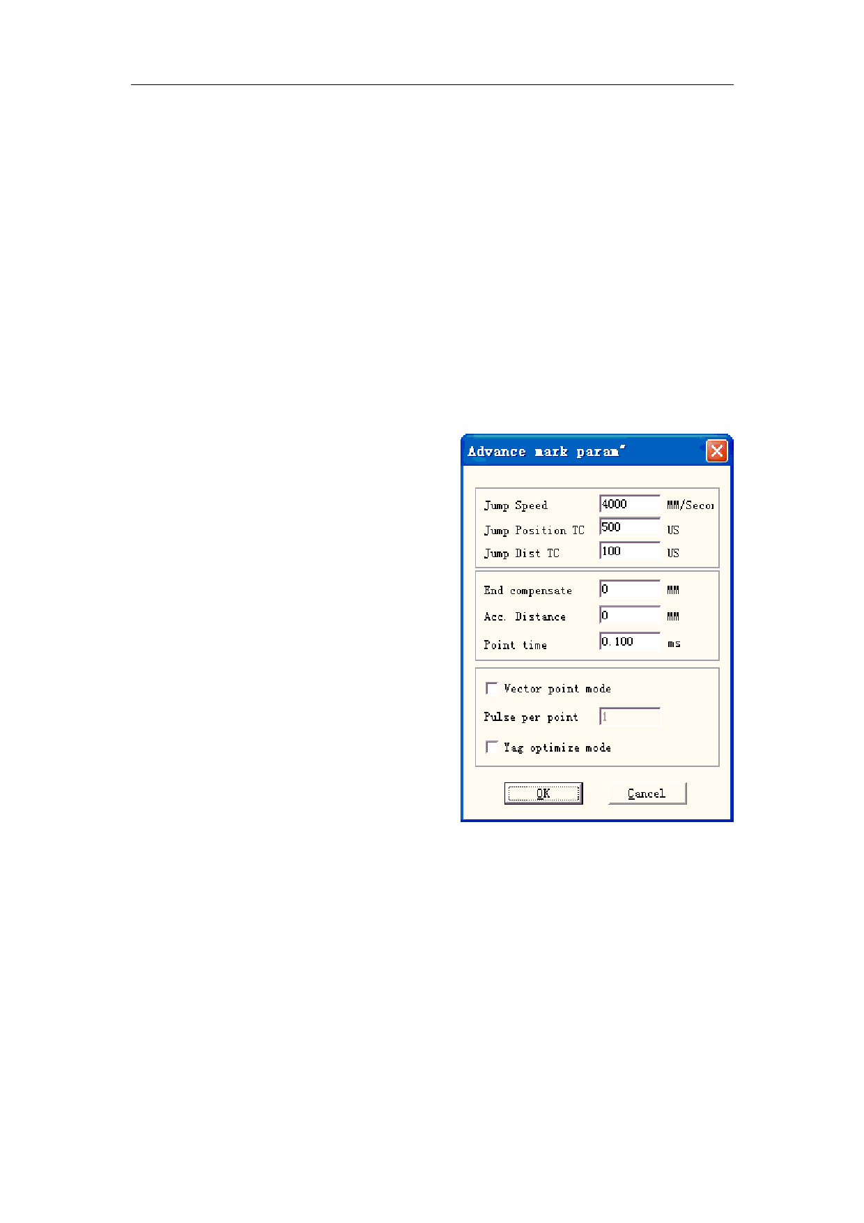
Clicking “Advanced” will prompt an advanced parameter dialog box as Figure 10-5 shows.
Jump Speed: set a jump speed of the scanner
for the current parameter
Jump Position TC | Jump Dist TC: After
each jump movement, the system will delay some
time then execute the next command. The actual
delay time is calculated by the following formula:
Total delay = (Jump Distance *Jump Dist TC) +
Jump Position TC
End compensate: Only when in high-speed
operation or this parameter need not to be set. This
parameter is used to mark a little bit more as an
ending increment at the end of an operation.
Negative value is supported.
Acc Distance: In those applications that
require laser marking without variation of intensity,
we have to add an accelerated segment before the
start point to reach the homogenous marking
results.
Point Time: This parameter is used to set the
marking time if there are dot objects.
Figure 10-5 Advanced
Vector point mode/Pulse per point: Marking the vector graph using point mode, and force
the pulse number while marking each point
YAG optimize mode: While marking on the high reflection material using YAG laser,
optimize the hatch arithmetic. Note: the function is used to resolve the irregular lines when
marking on the high reflection material using YAG laser. If you want to use this function, you
must connect the PWM signal to the pulse modulate signal of the Q-switch.
Now let’s take it into practice:
Mark a rectangle with size 40×20 and fill it with the following parameters: Mark Contour/
132
reserved
All rights
 LabelMark EZCAD V2 Software Manual")
 LabelMark EZCAD V2 Software Manual")
 LabelMark EZCAD V2 Software Manual")
 LabelMark EZCAD V2 Software Manual")
 LabelMark EZCAD V2 Software Manual")
 LabelMark EZCAD V2 Software Manual")
 LabelMark EZCAD V2 Software Manual")
 LabelMark EZCAD V2 Software Manual")
 LabelMark EZCAD V2 Software Manual")
 LabelMark EZCAD V2 Software Manual")
 LabelMark EZCAD V2 Software Manual")
 LabelMark EZCAD V2 Software Manual")
 LabelMark EZCAD V2 Software Manual")
 LabelMark EZCAD V2 Software Manual")
 LabelMark EZCAD V2 Software Manual")
 LabelMark EZCAD V2 Software Manual")
 LabelMark EZCAD V2 Software Manual")
 LabelMark EZCAD V2 Software Manual")
 LabelMark EZCAD V2 Software Manual")
 LabelMark EZCAD V2 Software Manual")
 LabelMark EZCAD V2 Software Manual")
 LabelMark EZCAD V2 Software Manual")
 LabelMark EZCAD V2 Software Manual")
 LabelMark EZCAD V2 Software Manual")
 LabelMark EZCAD V2 Software Manual")
 LabelMark EZCAD V2 Software Manual")
 LabelMark EZCAD V2 Software Manual")
 LabelMark EZCAD V2 Software Manual")
 LabelMark EZCAD V2 Software Manual")
 LabelMark EZCAD V2 Software Manual")
 LabelMark EZCAD V2 Software Manual")
 LabelMark EZCAD V2 Software Manual")
 LabelMark EZCAD V2 Software Manual")
 LabelMark EZCAD V2 Software Manual")
 LabelMark EZCAD V2 Software Manual")
 LabelMark EZCAD V2 Software Manual")
 LabelMark EZCAD V2 Software Manual")
 LabelMark EZCAD V2 Software Manual")
 LabelMark EZCAD V2 Software Manual")
 LabelMark EZCAD V2 Software Manual")
 LabelMark EZCAD V2 Software Manual")
 LabelMark EZCAD V2 Software Manual")
 LabelMark EZCAD V2 Software Manual")
 LabelMark EZCAD V2 Software Manual")
 LabelMark EZCAD V2 Software Manual")
 LabelMark EZCAD V2 Software Manual")
 LabelMark EZCAD V2 Software Manual")
 LabelMark EZCAD V2 Software Manual")
 LabelMark EZCAD V2 Software Manual")
 LabelMark EZCAD V2 Software Manual")
 LabelMark EZCAD V2 Software Manual")
 LabelMark EZCAD V2 Software Manual")
 LabelMark EZCAD V2 Software Manual")
 LabelMark EZCAD V2 Software Manual")
 LabelMark EZCAD V2 Software Manual")
 LabelMark EZCAD V2 Software Manual")
 LabelMark EZCAD V2 Software Manual")
 LabelMark EZCAD V2 Software Manual")
 LabelMark EZCAD V2 Software Manual")
 LabelMark EZCAD V2 Software Manual")
 LabelMark EZCAD V2 Software Manual")
 LabelMark EZCAD V2 Software Manual")
 LabelMark EZCAD V2 Software Manual")
 LabelMark EZCAD V2 Software Manual")
 LabelMark EZCAD V2 Software Manual")
 LabelMark EZCAD V2 Software Manual")
 LabelMark EZCAD V2 Software Manual")
 LabelMark EZCAD V2 Software Manual")
 LabelMark EZCAD V2 Software Manual")
 LabelMark EZCAD V2 Software Manual")
 LabelMark EZCAD V2 Software Manual")
 LabelMark EZCAD V2 Software Manual")
 LabelMark EZCAD V2 Software Manual")
 LabelMark EZCAD V2 Software Manual")
 LabelMark EZCAD V2 Software Manual")
 LabelMark EZCAD V2 Software Manual")
 LabelMark EZCAD V2 Software Manual")
 LabelMark EZCAD V2 Software Manual")
 LabelMark EZCAD V2 Software Manual")
 LabelMark EZCAD V2 Software Manual")
 LabelMark EZCAD V2 Software Manual")
 LabelMark EZCAD V2 Software Manual")
 LabelMark EZCAD V2 Software Manual")
 LabelMark EZCAD V2 Software Manual")
 LabelMark EZCAD V2 Software Manual")
 LabelMark EZCAD V2 Software Manual")
 LabelMark EZCAD V2 Software Manual")
 LabelMark EZCAD V2 Software Manual")
 LabelMark EZCAD V2 Software Manual")
 LabelMark EZCAD V2 Software Manual")
 LabelMark EZCAD V2 Software Manual")
 LabelMark EZCAD V2 Software Manual")
 LabelMark EZCAD V2 Software Manual")
 LabelMark EZCAD V2 Software Manual")
 LabelMark EZCAD V2 Software Manual")
 LabelMark EZCAD V2 Software Manual")
 LabelMark EZCAD V2 Software Manual")
 LabelMark EZCAD V2 Software Manual")
 LabelMark EZCAD V2 Software Manual")