
TMC2225 DATASHEET (Rev. 1.15 / 2023-FEB-16)
54
11 STEP/DIR Interface
The STEP and DIR inputs provide a simple, standard interface compatible with many existing motion
controllers. The MicroPlyer step pulse interpolator brings the smooth motor operation of high -
resolution microstepping to applications originally designed for coarser stepping.
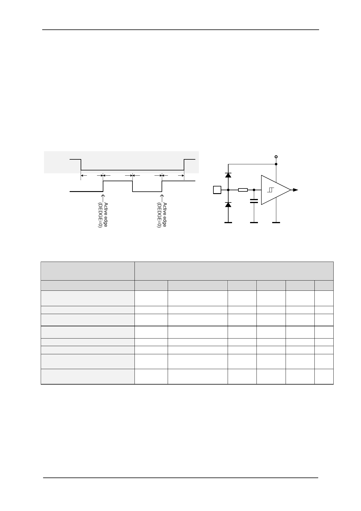
11.1 Timing
Figure 11.1 shows the timing parameters for the STEP and DIR signals, and the table below gives
their specifications. Only rising edges are active. STEP and DIR are sampled and synchronized to the
system clock. An internal analog filter removes glitches on the signals, such as those caused by long
PCB traces. If the signal source is far from the chip, and especially if the signals are carried on cables,
the signals should be filtered or differentially transmitted.
DIR
STEP
tDSU
tSH
tSL
tDSH
STEP
or DIR
Input
+VCC_IO
SchmittTrigger
83k
C
0.56 VCC_IO
0.44 VCC_IO
Internal
Signal
Figure 11.1 STEP and DIR timing, Input pin filter
Input filter
R*C = 20ns +-30%
STEP and DIR interface timing
Parameter
step frequency (at maximum
microstep resolution)
fullstep frequency
STEP input minimum low time
AC-Characteristics
clock period is tCLK
Symbol Conditions
fSTEP
fFS
tSL
STEP input minimum high time
tSH
DIR to STEP setup time
DIR after STEP hold time
STEP and DIR spike filtering time
*)
STEP and DIR sampling relative
to rising CLK input
tDSU
tDSH
tFILTSD
tSDCLKHI
rising and falling
edge
before rising edge
of CLK input
Min
Typ
max(tFILTSD,
tCLK+20)
max(tFILTSD,
tCLK+20)
20
20
13
100
100
20
tFILTSD
Max Unit
½ fCLK
fCLK/512
ns
ns
ns
ns
30
ns
ns
*) These values are valid with full input logic level swing, only. Asymmetric logic levels will increase
filtering delay tFILTSD, due to an internal input RC filter.
www.trinamic.com
 TMC2225 Power Driver for Stepper Motors Integrated Circuits Datasheet Rev1.15")
 TMC2225 Power Driver for Stepper Motors Integrated Circuits Datasheet Rev1.15")
 TMC2225 Power Driver for Stepper Motors Integrated Circuits Datasheet Rev1.15")
 TMC2225 Power Driver for Stepper Motors Integrated Circuits Datasheet Rev1.15")
 TMC2225 Power Driver for Stepper Motors Integrated Circuits Datasheet Rev1.15")
 TMC2225 Power Driver for Stepper Motors Integrated Circuits Datasheet Rev1.15")
 TMC2225 Power Driver for Stepper Motors Integrated Circuits Datasheet Rev1.15")
 TMC2225 Power Driver for Stepper Motors Integrated Circuits Datasheet Rev1.15")
 TMC2225 Power Driver for Stepper Motors Integrated Circuits Datasheet Rev1.15")
 TMC2225 Power Driver for Stepper Motors Integrated Circuits Datasheet Rev1.15")
 TMC2225 Power Driver for Stepper Motors Integrated Circuits Datasheet Rev1.15")
 TMC2225 Power Driver for Stepper Motors Integrated Circuits Datasheet Rev1.15")
 TMC2225 Power Driver for Stepper Motors Integrated Circuits Datasheet Rev1.15")
 TMC2225 Power Driver for Stepper Motors Integrated Circuits Datasheet Rev1.15")
 TMC2225 Power Driver for Stepper Motors Integrated Circuits Datasheet Rev1.15")
 TMC2225 Power Driver for Stepper Motors Integrated Circuits Datasheet Rev1.15")
 TMC2225 Power Driver for Stepper Motors Integrated Circuits Datasheet Rev1.15")
 TMC2225 Power Driver for Stepper Motors Integrated Circuits Datasheet Rev1.15")
 TMC2225 Power Driver for Stepper Motors Integrated Circuits Datasheet Rev1.15")
 TMC2225 Power Driver for Stepper Motors Integrated Circuits Datasheet Rev1.15")
 TMC2225 Power Driver for Stepper Motors Integrated Circuits Datasheet Rev1.15")
 TMC2225 Power Driver for Stepper Motors Integrated Circuits Datasheet Rev1.15")
 TMC2225 Power Driver for Stepper Motors Integrated Circuits Datasheet Rev1.15")
 TMC2225 Power Driver for Stepper Motors Integrated Circuits Datasheet Rev1.15")
 TMC2225 Power Driver for Stepper Motors Integrated Circuits Datasheet Rev1.15")
 TMC2225 Power Driver for Stepper Motors Integrated Circuits Datasheet Rev1.15")
 TMC2225 Power Driver for Stepper Motors Integrated Circuits Datasheet Rev1.15")
 TMC2225 Power Driver for Stepper Motors Integrated Circuits Datasheet Rev1.15")
 TMC2225 Power Driver for Stepper Motors Integrated Circuits Datasheet Rev1.15")
 TMC2225 Power Driver for Stepper Motors Integrated Circuits Datasheet Rev1.15")
 TMC2225 Power Driver for Stepper Motors Integrated Circuits Datasheet Rev1.15")
 TMC2225 Power Driver for Stepper Motors Integrated Circuits Datasheet Rev1.15")
 TMC2225 Power Driver for Stepper Motors Integrated Circuits Datasheet Rev1.15")
 TMC2225 Power Driver for Stepper Motors Integrated Circuits Datasheet Rev1.15")
 TMC2225 Power Driver for Stepper Motors Integrated Circuits Datasheet Rev1.15")
 TMC2225 Power Driver for Stepper Motors Integrated Circuits Datasheet Rev1.15")
 TMC2225 Power Driver for Stepper Motors Integrated Circuits Datasheet Rev1.15")
 TMC2225 Power Driver for Stepper Motors Integrated Circuits Datasheet Rev1.15")
 TMC2225 Power Driver for Stepper Motors Integrated Circuits Datasheet Rev1.15")
 TMC2225 Power Driver for Stepper Motors Integrated Circuits Datasheet Rev1.15")
 TMC2225 Power Driver for Stepper Motors Integrated Circuits Datasheet Rev1.15")
 TMC2225 Power Driver for Stepper Motors Integrated Circuits Datasheet Rev1.15")
 TMC2225 Power Driver for Stepper Motors Integrated Circuits Datasheet Rev1.15")
 TMC2225 Power Driver for Stepper Motors Integrated Circuits Datasheet Rev1.15")
 TMC2225 Power Driver for Stepper Motors Integrated Circuits Datasheet Rev1.15")
 TMC2225 Power Driver for Stepper Motors Integrated Circuits Datasheet Rev1.15")
 TMC2225 Power Driver for Stepper Motors Integrated Circuits Datasheet Rev1.15")
 TMC2225 Power Driver for Stepper Motors Integrated Circuits Datasheet Rev1.15")
 TMC2225 Power Driver for Stepper Motors Integrated Circuits Datasheet Rev1.15")
 TMC2225 Power Driver for Stepper Motors Integrated Circuits Datasheet Rev1.15")
 TMC2225 Power Driver for Stepper Motors Integrated Circuits Datasheet Rev1.15")
 TMC2225 Power Driver for Stepper Motors Integrated Circuits Datasheet Rev1.15")
 TMC2225 Power Driver for Stepper Motors Integrated Circuits Datasheet Rev1.15")
 TMC2225 Power Driver for Stepper Motors Integrated Circuits Datasheet Rev1.15")
 TMC2225 Power Driver for Stepper Motors Integrated Circuits Datasheet Rev1.15")
 TMC2225 Power Driver for Stepper Motors Integrated Circuits Datasheet Rev1.15")
 TMC2225 Power Driver for Stepper Motors Integrated Circuits Datasheet Rev1.15")
 TMC2225 Power Driver for Stepper Motors Integrated Circuits Datasheet Rev1.15")
 TMC2225 Power Driver for Stepper Motors Integrated Circuits Datasheet Rev1.15")
 TMC2225 Power Driver for Stepper Motors Integrated Circuits Datasheet Rev1.15")
 TMC2225 Power Driver for Stepper Motors Integrated Circuits Datasheet Rev1.15")
 TMC2225 Power Driver for Stepper Motors Integrated Circuits Datasheet Rev1.15")
 TMC2225 Power Driver for Stepper Motors Integrated Circuits Datasheet Rev1.15")
 TMC2225 Power Driver for Stepper Motors Integrated Circuits Datasheet Rev1.15")
 TMC2225 Power Driver for Stepper Motors Integrated Circuits Datasheet Rev1.15")
 TMC2225 Power Driver for Stepper Motors Integrated Circuits Datasheet Rev1.15")
 TMC2225 Power Driver for Stepper Motors Integrated Circuits Datasheet Rev1.15")
 TMC2225 Power Driver for Stepper Motors Integrated Circuits Datasheet Rev1.15")
 TMC2225 Power Driver for Stepper Motors Integrated Circuits Datasheet Rev1.15")
 TMC2225 Power Driver for Stepper Motors Integrated Circuits Datasheet Rev1.15")
 TMC2225 Power Driver for Stepper Motors Integrated Circuits Datasheet Rev1.15")
 TMC2225 Power Driver for Stepper Motors Integrated Circuits Datasheet Rev1.15")
 TMC2225 Power Driver for Stepper Motors Integrated Circuits Datasheet Rev1.15")
 TMC2225 Power Driver for Stepper Motors Integrated Circuits Datasheet Rev1.15")
 TMC2225 Power Driver for Stepper Motors Integrated Circuits Datasheet Rev1.15")
 TMC2225 Power Driver for Stepper Motors Integrated Circuits Datasheet Rev1.15")