
TMC2225 DATASHEET (Rev. 1.15 / 2023-FEB-16)
48
8 Selecting Sense Resistors
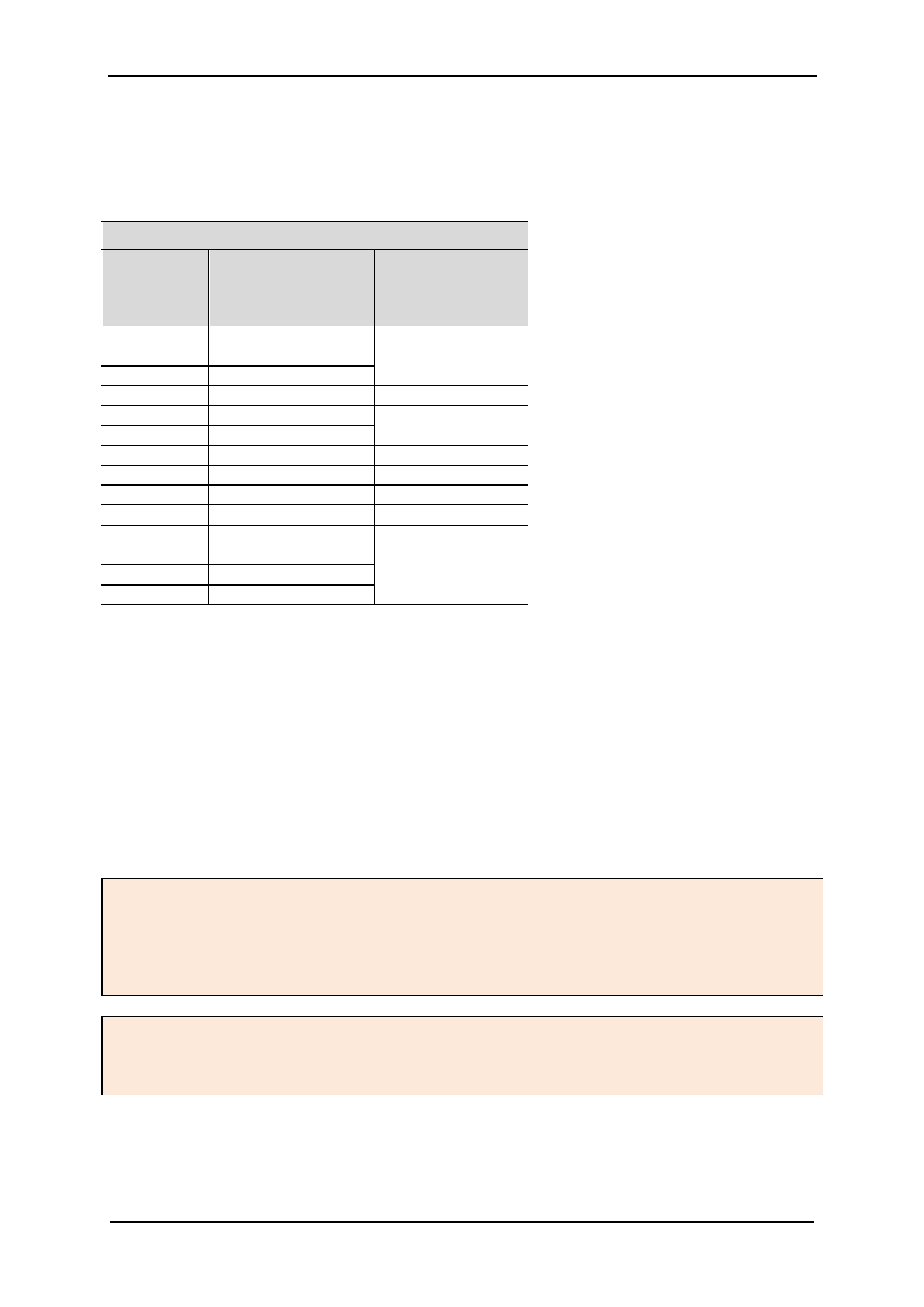
Set the desired maximum motor current by selecting an appropriate value for the sense resistor. The
following table shows the RMS current values which can be reached using standard resistors and
motor types fitting without additional motor current scaling.
CHOICE OF RSENSE AND RESULTING MAX. MOTOR CURRENT
RSENSE [Ω]
RMS current [A]
Fitting motor type
VREF=2.5V (or open), (examples)
IRUN=31,
vsense=0 (standard)
1.00
0.22
0.82
0.27
0.75
0.29
300mA motor
0.68
0.32
400mA motor
0.50
0.43
470m
0.46
500mA motor
390m
0.55
600mA motor
330m
0.64
700mA motor
270m
0.77
800mA motor
220m
0.92
1A motor
180m
1.09
1.2A motor
150m
1.28
120m
1.53*)
100m
1.77*)
1.5A motor
*) Value exceeds upper current rating, scaling down required, e.g. by reduced VREF.
Sense resistors should be carefully selected. The full motor current flows through the sense resistors.
Due to chopper operation the sense resistors see pulsed current from the MOSFET bridges. Therefore,
a low-inductance type such as film or composition resistors is required to prevent voltage spikes
causing ringing on the sense voltage inputs leading to unstable measurement results. A lso, a low-
inductance, low-resistance PCB layout is essential. Any common GND path for the two sense resistors
must be avoided, because this would lead to coupling between the two current sense signals. A
massive ground plane is best. Please also refer to layout considerations in chapter 19.
The sense resistor needs to be able to conduct the peak motor coil current in motor standstill
conditions, unless standby power is reduced. Under normal conditions, the sense resistor conducts
less than the coil RMS current, because no current flows through the sense resistor during the slow
decay phases. A 0.5W type is sufficient for most applications up to 1.2A RMS current.
Attention
Properly select sense resistors especially for applications, where the EN N pin is fixed to an active
level, because the full current for default setting IRUN=31 will flow through the motor right after
power up for a short moment, until the driver goes to hold current reduction, or a lower setting has
been issued via UART. Too low resistor values not matching the motor, thus lead to a significant
increase in supply current, up to the current limit determined by the motor coil resistance.
Attention
Be sure to use a symmetrical sense resistor layout and short and straight sense resistor traces of
identical length. Well matching sense resistors ensure best performance.
A compact layout with massive ground plane is best to avoid parasitic resistance effects.
www.trinamic.com
 TMC2225 Power Driver for Stepper Motors Integrated Circuits Datasheet Rev1.15")
 TMC2225 Power Driver for Stepper Motors Integrated Circuits Datasheet Rev1.15")
 TMC2225 Power Driver for Stepper Motors Integrated Circuits Datasheet Rev1.15")
 TMC2225 Power Driver for Stepper Motors Integrated Circuits Datasheet Rev1.15")
 TMC2225 Power Driver for Stepper Motors Integrated Circuits Datasheet Rev1.15")
 TMC2225 Power Driver for Stepper Motors Integrated Circuits Datasheet Rev1.15")
 TMC2225 Power Driver for Stepper Motors Integrated Circuits Datasheet Rev1.15")
 TMC2225 Power Driver for Stepper Motors Integrated Circuits Datasheet Rev1.15")
 TMC2225 Power Driver for Stepper Motors Integrated Circuits Datasheet Rev1.15")
 TMC2225 Power Driver for Stepper Motors Integrated Circuits Datasheet Rev1.15")
 TMC2225 Power Driver for Stepper Motors Integrated Circuits Datasheet Rev1.15")
 TMC2225 Power Driver for Stepper Motors Integrated Circuits Datasheet Rev1.15")
 TMC2225 Power Driver for Stepper Motors Integrated Circuits Datasheet Rev1.15")
 TMC2225 Power Driver for Stepper Motors Integrated Circuits Datasheet Rev1.15")
 TMC2225 Power Driver for Stepper Motors Integrated Circuits Datasheet Rev1.15")
 TMC2225 Power Driver for Stepper Motors Integrated Circuits Datasheet Rev1.15")
 TMC2225 Power Driver for Stepper Motors Integrated Circuits Datasheet Rev1.15")
 TMC2225 Power Driver for Stepper Motors Integrated Circuits Datasheet Rev1.15")
 TMC2225 Power Driver for Stepper Motors Integrated Circuits Datasheet Rev1.15")
 TMC2225 Power Driver for Stepper Motors Integrated Circuits Datasheet Rev1.15")
 TMC2225 Power Driver for Stepper Motors Integrated Circuits Datasheet Rev1.15")
 TMC2225 Power Driver for Stepper Motors Integrated Circuits Datasheet Rev1.15")
 TMC2225 Power Driver for Stepper Motors Integrated Circuits Datasheet Rev1.15")
 TMC2225 Power Driver for Stepper Motors Integrated Circuits Datasheet Rev1.15")
 TMC2225 Power Driver for Stepper Motors Integrated Circuits Datasheet Rev1.15")
 TMC2225 Power Driver for Stepper Motors Integrated Circuits Datasheet Rev1.15")
 TMC2225 Power Driver for Stepper Motors Integrated Circuits Datasheet Rev1.15")
 TMC2225 Power Driver for Stepper Motors Integrated Circuits Datasheet Rev1.15")
 TMC2225 Power Driver for Stepper Motors Integrated Circuits Datasheet Rev1.15")
 TMC2225 Power Driver for Stepper Motors Integrated Circuits Datasheet Rev1.15")
 TMC2225 Power Driver for Stepper Motors Integrated Circuits Datasheet Rev1.15")
 TMC2225 Power Driver for Stepper Motors Integrated Circuits Datasheet Rev1.15")
 TMC2225 Power Driver for Stepper Motors Integrated Circuits Datasheet Rev1.15")
 TMC2225 Power Driver for Stepper Motors Integrated Circuits Datasheet Rev1.15")
 TMC2225 Power Driver for Stepper Motors Integrated Circuits Datasheet Rev1.15")
 TMC2225 Power Driver for Stepper Motors Integrated Circuits Datasheet Rev1.15")
 TMC2225 Power Driver for Stepper Motors Integrated Circuits Datasheet Rev1.15")
 TMC2225 Power Driver for Stepper Motors Integrated Circuits Datasheet Rev1.15")
 TMC2225 Power Driver for Stepper Motors Integrated Circuits Datasheet Rev1.15")
 TMC2225 Power Driver for Stepper Motors Integrated Circuits Datasheet Rev1.15")
 TMC2225 Power Driver for Stepper Motors Integrated Circuits Datasheet Rev1.15")
 TMC2225 Power Driver for Stepper Motors Integrated Circuits Datasheet Rev1.15")
 TMC2225 Power Driver for Stepper Motors Integrated Circuits Datasheet Rev1.15")
 TMC2225 Power Driver for Stepper Motors Integrated Circuits Datasheet Rev1.15")
 TMC2225 Power Driver for Stepper Motors Integrated Circuits Datasheet Rev1.15")
 TMC2225 Power Driver for Stepper Motors Integrated Circuits Datasheet Rev1.15")
 TMC2225 Power Driver for Stepper Motors Integrated Circuits Datasheet Rev1.15")
 TMC2225 Power Driver for Stepper Motors Integrated Circuits Datasheet Rev1.15")
 TMC2225 Power Driver for Stepper Motors Integrated Circuits Datasheet Rev1.15")
 TMC2225 Power Driver for Stepper Motors Integrated Circuits Datasheet Rev1.15")
 TMC2225 Power Driver for Stepper Motors Integrated Circuits Datasheet Rev1.15")
 TMC2225 Power Driver for Stepper Motors Integrated Circuits Datasheet Rev1.15")
 TMC2225 Power Driver for Stepper Motors Integrated Circuits Datasheet Rev1.15")
 TMC2225 Power Driver for Stepper Motors Integrated Circuits Datasheet Rev1.15")
 TMC2225 Power Driver for Stepper Motors Integrated Circuits Datasheet Rev1.15")
 TMC2225 Power Driver for Stepper Motors Integrated Circuits Datasheet Rev1.15")
 TMC2225 Power Driver for Stepper Motors Integrated Circuits Datasheet Rev1.15")
 TMC2225 Power Driver for Stepper Motors Integrated Circuits Datasheet Rev1.15")
 TMC2225 Power Driver for Stepper Motors Integrated Circuits Datasheet Rev1.15")
 TMC2225 Power Driver for Stepper Motors Integrated Circuits Datasheet Rev1.15")
 TMC2225 Power Driver for Stepper Motors Integrated Circuits Datasheet Rev1.15")
 TMC2225 Power Driver for Stepper Motors Integrated Circuits Datasheet Rev1.15")
 TMC2225 Power Driver for Stepper Motors Integrated Circuits Datasheet Rev1.15")
 TMC2225 Power Driver for Stepper Motors Integrated Circuits Datasheet Rev1.15")
 TMC2225 Power Driver for Stepper Motors Integrated Circuits Datasheet Rev1.15")
 TMC2225 Power Driver for Stepper Motors Integrated Circuits Datasheet Rev1.15")
 TMC2225 Power Driver for Stepper Motors Integrated Circuits Datasheet Rev1.15")
 TMC2225 Power Driver for Stepper Motors Integrated Circuits Datasheet Rev1.15")
 TMC2225 Power Driver for Stepper Motors Integrated Circuits Datasheet Rev1.15")
 TMC2225 Power Driver for Stepper Motors Integrated Circuits Datasheet Rev1.15")
 TMC2225 Power Driver for Stepper Motors Integrated Circuits Datasheet Rev1.15")
 TMC2225 Power Driver for Stepper Motors Integrated Circuits Datasheet Rev1.15")
 TMC2225 Power Driver for Stepper Motors Integrated Circuits Datasheet Rev1.15")
 TMC2225 Power Driver for Stepper Motors Integrated Circuits Datasheet Rev1.15")
 TMC2225 Power Driver for Stepper Motors Integrated Circuits Datasheet Rev1.15")
 TMC2225 Power Driver for Stepper Motors Integrated Circuits Datasheet Rev1.15")