
TMC2225 DATASHEET (Rev. 1.15 / 2023-FEB-16)
16
The UART line must be logic high during idle state. Therefore, the power down function cannot be
assigned by the pin PDN_UART in between of transmissions. In an application using the UART
interface, set the desired power down function by register access and set pdn_disable in GCONF to
disable the pin function.
4.1.2 Read Access
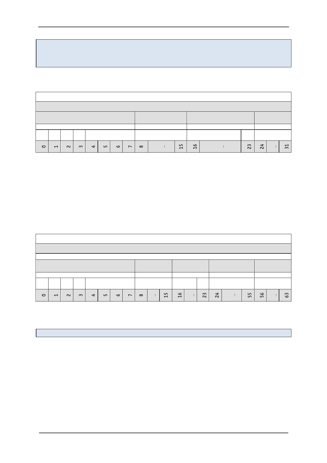
UART READ ACCESS REQUEST DATAGRAM STRUCTURE
each byte is LSB…MSB, highest byte transmitted first
sync + reserved
8 bit node address
0...7
1
0
1
0
Reserved (don’t cares
but included in CRC)
8…15
NODEADDR=0
RW + 7 bit register
address
16…23
register address
0
CRC
24…31
CRC
The read access request datagram structure is identical to the write access datagram structure, but
uses a lower number of user bits. Its function is the addressing of the node and the transmission of
the desired register address for the read access. The TMC2225 responds with the same baud rate as
the master uses for the read request.
In order to ensure a clean bus transition from the master to the node, the TMC2225 does not
immediately send the reply to a read access, but it uses a programmable delay time after which the
first reply byte becomes sent following a read request. This delay time can be set in multiples of
eight bit times using SENDDELAY time setting (default=8 bit times) according to the needs of the
master.
UART READ ACCESS REPLY DATAGRAM STRUCTURE
each byte is LSB…MSB, highest byte transmitted first
sync + reserved
0…7
1 01 0
reserved (0)
0 ...... 63
8 bit master RW + 7 bit
address
register addr.
8…15
16…23
0xFF
register
address
0
32 bit data
24…55
data bytes 3, 2, 1, 0
(high to low byte)
CRC
56…63
CRC
The read response is sent to the master using address code %1111 1111. The transmitter becomes
switched inactive four bit times after the last bit is sent.
Address %11111111 is reserved for read access replies going to the master.
www.trinamic.com
 TMC2225 Power Driver for Stepper Motors Integrated Circuits Datasheet Rev1.15")
 TMC2225 Power Driver for Stepper Motors Integrated Circuits Datasheet Rev1.15")
 TMC2225 Power Driver for Stepper Motors Integrated Circuits Datasheet Rev1.15")
 TMC2225 Power Driver for Stepper Motors Integrated Circuits Datasheet Rev1.15")
 TMC2225 Power Driver for Stepper Motors Integrated Circuits Datasheet Rev1.15")
 TMC2225 Power Driver for Stepper Motors Integrated Circuits Datasheet Rev1.15")
 TMC2225 Power Driver for Stepper Motors Integrated Circuits Datasheet Rev1.15")
 TMC2225 Power Driver for Stepper Motors Integrated Circuits Datasheet Rev1.15")
 TMC2225 Power Driver for Stepper Motors Integrated Circuits Datasheet Rev1.15")
 TMC2225 Power Driver for Stepper Motors Integrated Circuits Datasheet Rev1.15")
 TMC2225 Power Driver for Stepper Motors Integrated Circuits Datasheet Rev1.15")
 TMC2225 Power Driver for Stepper Motors Integrated Circuits Datasheet Rev1.15")
 TMC2225 Power Driver for Stepper Motors Integrated Circuits Datasheet Rev1.15")
 TMC2225 Power Driver for Stepper Motors Integrated Circuits Datasheet Rev1.15")
 TMC2225 Power Driver for Stepper Motors Integrated Circuits Datasheet Rev1.15")
 TMC2225 Power Driver for Stepper Motors Integrated Circuits Datasheet Rev1.15")
 TMC2225 Power Driver for Stepper Motors Integrated Circuits Datasheet Rev1.15")
 TMC2225 Power Driver for Stepper Motors Integrated Circuits Datasheet Rev1.15")
 TMC2225 Power Driver for Stepper Motors Integrated Circuits Datasheet Rev1.15")
 TMC2225 Power Driver for Stepper Motors Integrated Circuits Datasheet Rev1.15")
 TMC2225 Power Driver for Stepper Motors Integrated Circuits Datasheet Rev1.15")
 TMC2225 Power Driver for Stepper Motors Integrated Circuits Datasheet Rev1.15")
 TMC2225 Power Driver for Stepper Motors Integrated Circuits Datasheet Rev1.15")
 TMC2225 Power Driver for Stepper Motors Integrated Circuits Datasheet Rev1.15")
 TMC2225 Power Driver for Stepper Motors Integrated Circuits Datasheet Rev1.15")
 TMC2225 Power Driver for Stepper Motors Integrated Circuits Datasheet Rev1.15")
 TMC2225 Power Driver for Stepper Motors Integrated Circuits Datasheet Rev1.15")
 TMC2225 Power Driver for Stepper Motors Integrated Circuits Datasheet Rev1.15")
 TMC2225 Power Driver for Stepper Motors Integrated Circuits Datasheet Rev1.15")
 TMC2225 Power Driver for Stepper Motors Integrated Circuits Datasheet Rev1.15")
 TMC2225 Power Driver for Stepper Motors Integrated Circuits Datasheet Rev1.15")
 TMC2225 Power Driver for Stepper Motors Integrated Circuits Datasheet Rev1.15")
 TMC2225 Power Driver for Stepper Motors Integrated Circuits Datasheet Rev1.15")
 TMC2225 Power Driver for Stepper Motors Integrated Circuits Datasheet Rev1.15")
 TMC2225 Power Driver for Stepper Motors Integrated Circuits Datasheet Rev1.15")
 TMC2225 Power Driver for Stepper Motors Integrated Circuits Datasheet Rev1.15")
 TMC2225 Power Driver for Stepper Motors Integrated Circuits Datasheet Rev1.15")
 TMC2225 Power Driver for Stepper Motors Integrated Circuits Datasheet Rev1.15")
 TMC2225 Power Driver for Stepper Motors Integrated Circuits Datasheet Rev1.15")
 TMC2225 Power Driver for Stepper Motors Integrated Circuits Datasheet Rev1.15")
 TMC2225 Power Driver for Stepper Motors Integrated Circuits Datasheet Rev1.15")
 TMC2225 Power Driver for Stepper Motors Integrated Circuits Datasheet Rev1.15")
 TMC2225 Power Driver for Stepper Motors Integrated Circuits Datasheet Rev1.15")
 TMC2225 Power Driver for Stepper Motors Integrated Circuits Datasheet Rev1.15")
 TMC2225 Power Driver for Stepper Motors Integrated Circuits Datasheet Rev1.15")
 TMC2225 Power Driver for Stepper Motors Integrated Circuits Datasheet Rev1.15")
 TMC2225 Power Driver for Stepper Motors Integrated Circuits Datasheet Rev1.15")
 TMC2225 Power Driver for Stepper Motors Integrated Circuits Datasheet Rev1.15")
 TMC2225 Power Driver for Stepper Motors Integrated Circuits Datasheet Rev1.15")
 TMC2225 Power Driver for Stepper Motors Integrated Circuits Datasheet Rev1.15")
 TMC2225 Power Driver for Stepper Motors Integrated Circuits Datasheet Rev1.15")
 TMC2225 Power Driver for Stepper Motors Integrated Circuits Datasheet Rev1.15")
 TMC2225 Power Driver for Stepper Motors Integrated Circuits Datasheet Rev1.15")
 TMC2225 Power Driver for Stepper Motors Integrated Circuits Datasheet Rev1.15")
 TMC2225 Power Driver for Stepper Motors Integrated Circuits Datasheet Rev1.15")
 TMC2225 Power Driver for Stepper Motors Integrated Circuits Datasheet Rev1.15")
 TMC2225 Power Driver for Stepper Motors Integrated Circuits Datasheet Rev1.15")
 TMC2225 Power Driver for Stepper Motors Integrated Circuits Datasheet Rev1.15")
 TMC2225 Power Driver for Stepper Motors Integrated Circuits Datasheet Rev1.15")
 TMC2225 Power Driver for Stepper Motors Integrated Circuits Datasheet Rev1.15")
 TMC2225 Power Driver for Stepper Motors Integrated Circuits Datasheet Rev1.15")
 TMC2225 Power Driver for Stepper Motors Integrated Circuits Datasheet Rev1.15")
 TMC2225 Power Driver for Stepper Motors Integrated Circuits Datasheet Rev1.15")
 TMC2225 Power Driver for Stepper Motors Integrated Circuits Datasheet Rev1.15")
 TMC2225 Power Driver for Stepper Motors Integrated Circuits Datasheet Rev1.15")
 TMC2225 Power Driver for Stepper Motors Integrated Circuits Datasheet Rev1.15")
 TMC2225 Power Driver for Stepper Motors Integrated Circuits Datasheet Rev1.15")
 TMC2225 Power Driver for Stepper Motors Integrated Circuits Datasheet Rev1.15")
 TMC2225 Power Driver for Stepper Motors Integrated Circuits Datasheet Rev1.15")
 TMC2225 Power Driver for Stepper Motors Integrated Circuits Datasheet Rev1.15")
 TMC2225 Power Driver for Stepper Motors Integrated Circuits Datasheet Rev1.15")
 TMC2225 Power Driver for Stepper Motors Integrated Circuits Datasheet Rev1.15")
 TMC2225 Power Driver for Stepper Motors Integrated Circuits Datasheet Rev1.15")
 TMC2225 Power Driver for Stepper Motors Integrated Circuits Datasheet Rev1.15")
 TMC2225 Power Driver for Stepper Motors Integrated Circuits Datasheet Rev1.15")
 TMC2225 Power Driver for Stepper Motors Integrated Circuits Datasheet Rev1.15")