
TMC2225 DATASHEET (Rev. 1.15 / 2023-FEB-16)
11
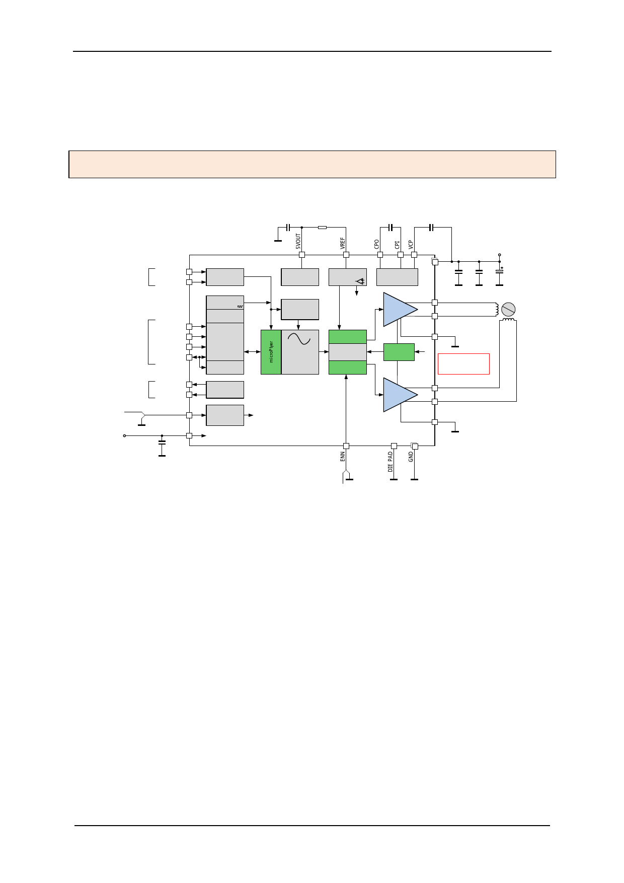
3.2 Internal RDSon Sensing
For cost critical or space limited applications, sense resistors can be omitted. For internal current
sensing, a reference current set by a tiny external resistor programs the output current. For calculation
of the reference resistor, refer chapter 9.1.
Attention
Be sure to switch the IC to RDSon mode, before enabling drivers: Set otp_internalRsense = 1.
Place near IC with
short path to die pad
2.2µ
6.3V
RREF
Step and Direction
motion control
TMC2225
STEP
DIR
Step&Dir input
Configuration
(GND/open or VCC_IO)
optional UART interface
MS1
MS2
SPREAD
(only TMC222x)
PDN/UART
Driver error
Index pulse
opt. ext. clock
10-16MHz
3.3V or 5V
I/O voltage
DIAG
INDEX
(not with TMC2202)
CLK_IN
VCC_IO
100n
Step Pulse
Generator
Configuration
Memory (OTP)
Configuration
Interface
B. Dwersteg, ©
TRINAMIC 2016
UART interface
+ Register Block
Programmable
Diagnostic
Outputs
Trimmed
CLK oscillator/
selector
5V Voltage
regulator
Stand Still
Current
Reduction
Analog Scaling
VREF IREF
256 Microstep
Sequencer
stealthChop2
Driver
spreadCycle
22n
50V
charge pump
Full Bridge A
100n
16V
VS
+VM
100n
100n
100µF
Low ESR type
OA1
OA2
N
S
stepper
motor
Integrated IREF
Rsense
Full Bridge B
BRA
Connect directly
to GND plane
Attention:
Start with ENN=high!
Set GCONF.1 or OTP0.6
prior to enabling the driver!
OB1
OB2
BRB
Connect directly
to GND plane
opt. driver enable
Figure 3.2 Application circuit using RDSon based sensing
www.trinamic.com
 TMC2225 Power Driver for Stepper Motors Integrated Circuits Datasheet Rev1.15")
 TMC2225 Power Driver for Stepper Motors Integrated Circuits Datasheet Rev1.15")
 TMC2225 Power Driver for Stepper Motors Integrated Circuits Datasheet Rev1.15")
 TMC2225 Power Driver for Stepper Motors Integrated Circuits Datasheet Rev1.15")
 TMC2225 Power Driver for Stepper Motors Integrated Circuits Datasheet Rev1.15")
 TMC2225 Power Driver for Stepper Motors Integrated Circuits Datasheet Rev1.15")
 TMC2225 Power Driver for Stepper Motors Integrated Circuits Datasheet Rev1.15")
 TMC2225 Power Driver for Stepper Motors Integrated Circuits Datasheet Rev1.15")
 TMC2225 Power Driver for Stepper Motors Integrated Circuits Datasheet Rev1.15")
 TMC2225 Power Driver for Stepper Motors Integrated Circuits Datasheet Rev1.15")
 TMC2225 Power Driver for Stepper Motors Integrated Circuits Datasheet Rev1.15")
 TMC2225 Power Driver for Stepper Motors Integrated Circuits Datasheet Rev1.15")
 TMC2225 Power Driver for Stepper Motors Integrated Circuits Datasheet Rev1.15")
 TMC2225 Power Driver for Stepper Motors Integrated Circuits Datasheet Rev1.15")
 TMC2225 Power Driver for Stepper Motors Integrated Circuits Datasheet Rev1.15")
 TMC2225 Power Driver for Stepper Motors Integrated Circuits Datasheet Rev1.15")
 TMC2225 Power Driver for Stepper Motors Integrated Circuits Datasheet Rev1.15")
 TMC2225 Power Driver for Stepper Motors Integrated Circuits Datasheet Rev1.15")
 TMC2225 Power Driver for Stepper Motors Integrated Circuits Datasheet Rev1.15")
 TMC2225 Power Driver for Stepper Motors Integrated Circuits Datasheet Rev1.15")
 TMC2225 Power Driver for Stepper Motors Integrated Circuits Datasheet Rev1.15")
 TMC2225 Power Driver for Stepper Motors Integrated Circuits Datasheet Rev1.15")
 TMC2225 Power Driver for Stepper Motors Integrated Circuits Datasheet Rev1.15")
 TMC2225 Power Driver for Stepper Motors Integrated Circuits Datasheet Rev1.15")
 TMC2225 Power Driver for Stepper Motors Integrated Circuits Datasheet Rev1.15")
 TMC2225 Power Driver for Stepper Motors Integrated Circuits Datasheet Rev1.15")
 TMC2225 Power Driver for Stepper Motors Integrated Circuits Datasheet Rev1.15")
 TMC2225 Power Driver for Stepper Motors Integrated Circuits Datasheet Rev1.15")
 TMC2225 Power Driver for Stepper Motors Integrated Circuits Datasheet Rev1.15")
 TMC2225 Power Driver for Stepper Motors Integrated Circuits Datasheet Rev1.15")
 TMC2225 Power Driver for Stepper Motors Integrated Circuits Datasheet Rev1.15")
 TMC2225 Power Driver for Stepper Motors Integrated Circuits Datasheet Rev1.15")
 TMC2225 Power Driver for Stepper Motors Integrated Circuits Datasheet Rev1.15")
 TMC2225 Power Driver for Stepper Motors Integrated Circuits Datasheet Rev1.15")
 TMC2225 Power Driver for Stepper Motors Integrated Circuits Datasheet Rev1.15")
 TMC2225 Power Driver for Stepper Motors Integrated Circuits Datasheet Rev1.15")
 TMC2225 Power Driver for Stepper Motors Integrated Circuits Datasheet Rev1.15")
 TMC2225 Power Driver for Stepper Motors Integrated Circuits Datasheet Rev1.15")
 TMC2225 Power Driver for Stepper Motors Integrated Circuits Datasheet Rev1.15")
 TMC2225 Power Driver for Stepper Motors Integrated Circuits Datasheet Rev1.15")
 TMC2225 Power Driver for Stepper Motors Integrated Circuits Datasheet Rev1.15")
 TMC2225 Power Driver for Stepper Motors Integrated Circuits Datasheet Rev1.15")
 TMC2225 Power Driver for Stepper Motors Integrated Circuits Datasheet Rev1.15")
 TMC2225 Power Driver for Stepper Motors Integrated Circuits Datasheet Rev1.15")
 TMC2225 Power Driver for Stepper Motors Integrated Circuits Datasheet Rev1.15")
 TMC2225 Power Driver for Stepper Motors Integrated Circuits Datasheet Rev1.15")
 TMC2225 Power Driver for Stepper Motors Integrated Circuits Datasheet Rev1.15")
 TMC2225 Power Driver for Stepper Motors Integrated Circuits Datasheet Rev1.15")
 TMC2225 Power Driver for Stepper Motors Integrated Circuits Datasheet Rev1.15")
 TMC2225 Power Driver for Stepper Motors Integrated Circuits Datasheet Rev1.15")
 TMC2225 Power Driver for Stepper Motors Integrated Circuits Datasheet Rev1.15")
 TMC2225 Power Driver for Stepper Motors Integrated Circuits Datasheet Rev1.15")
 TMC2225 Power Driver for Stepper Motors Integrated Circuits Datasheet Rev1.15")
 TMC2225 Power Driver for Stepper Motors Integrated Circuits Datasheet Rev1.15")
 TMC2225 Power Driver for Stepper Motors Integrated Circuits Datasheet Rev1.15")
 TMC2225 Power Driver for Stepper Motors Integrated Circuits Datasheet Rev1.15")
 TMC2225 Power Driver for Stepper Motors Integrated Circuits Datasheet Rev1.15")
 TMC2225 Power Driver for Stepper Motors Integrated Circuits Datasheet Rev1.15")
 TMC2225 Power Driver for Stepper Motors Integrated Circuits Datasheet Rev1.15")
 TMC2225 Power Driver for Stepper Motors Integrated Circuits Datasheet Rev1.15")
 TMC2225 Power Driver for Stepper Motors Integrated Circuits Datasheet Rev1.15")
 TMC2225 Power Driver for Stepper Motors Integrated Circuits Datasheet Rev1.15")
 TMC2225 Power Driver for Stepper Motors Integrated Circuits Datasheet Rev1.15")
 TMC2225 Power Driver for Stepper Motors Integrated Circuits Datasheet Rev1.15")
 TMC2225 Power Driver for Stepper Motors Integrated Circuits Datasheet Rev1.15")
 TMC2225 Power Driver for Stepper Motors Integrated Circuits Datasheet Rev1.15")
 TMC2225 Power Driver for Stepper Motors Integrated Circuits Datasheet Rev1.15")
 TMC2225 Power Driver for Stepper Motors Integrated Circuits Datasheet Rev1.15")
 TMC2225 Power Driver for Stepper Motors Integrated Circuits Datasheet Rev1.15")
 TMC2225 Power Driver for Stepper Motors Integrated Circuits Datasheet Rev1.15")
 TMC2225 Power Driver for Stepper Motors Integrated Circuits Datasheet Rev1.15")
 TMC2225 Power Driver for Stepper Motors Integrated Circuits Datasheet Rev1.15")
 TMC2225 Power Driver for Stepper Motors Integrated Circuits Datasheet Rev1.15")
 TMC2225 Power Driver for Stepper Motors Integrated Circuits Datasheet Rev1.15")
 TMC2225 Power Driver for Stepper Motors Integrated Circuits Datasheet Rev1.15")
 TMC2225 Power Driver for Stepper Motors Integrated Circuits Datasheet Rev1.15")