
TMC2225 DATASHEET (Rev. 1.15 / 2023-FEB-16)
14
the smoothness of operation, as it does not impact the critical current zero transition. The effect does
not occur with StealthChop.
3.6 Driver Protection and EME Circuitry
Some applications have to cope with ESD events caused by motor operation or external influence.
Despite ESD circuitry within the driver chips, ESD events occurring during operation can cause a reset
or even a destruction of the motor driver, depending on their energy. Especially plastic housings and
belt drive systems tend to cause ESD events of several kV. It is best practice to avoid ESD events by
attaching all conductive parts, especially the motors themselves to PCB ground, or to apply electrically
conductive plastic parts. In addition, the driver can be protected up to a certain degree against ESD
events or live plugging / pulling the motor, which also causes high voltages and high currents into
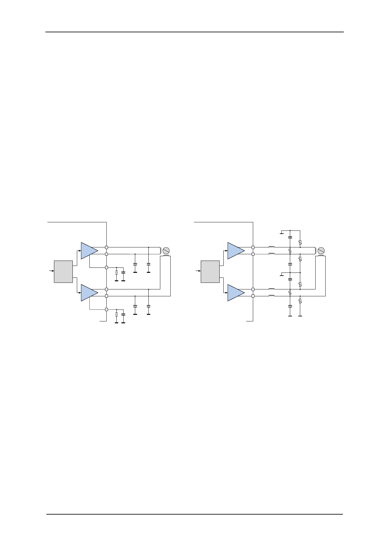
the motor connector terminals. A simple scheme uses capacitors at the driver outputs to re duce the
dV/dt caused by ESD events. Larger capacitors will bring more benefit concerning ESD suppression,
but cause additional current flow in each chopper cycle, and thus increase driver power dissipation,
especially at high supply voltages. The values shown are example values – they may be varied
between 100pF and 1nF. The capacitors also dampen high frequency noise injected from digital parts
of the application PCB circuitry and thus reduce electromagnetic emission. A more elaborate scheme
uses LC filters to de-couple the driver outputs from the motor connector. Varistors in between of the
coil terminals eliminate coil overvoltage caused by live plugging. Optionally protect all outputs by a
varistor to GND against ESD voltage.
Driver
Full Bridge A
Full Bridge B
OA1
OA2
BRA
RSA
100nF
16V
470pF
100V
470pF
100V
N
S
stepper
motor
OB1
OB2
BRB
RSB
100nF
16V
470pF
100V
470pF
100V
Driver
Full Bridge A
Full Bridge B
OA1
OA2
50Ohm @
100MHz
50Ohm @
100MHz
470pF
100V
V1A
V1
V1B
470pF
100V
N
S
stepper
motor
OB1
OB2
50Ohm @
100MHz
50Ohm @
100MHz
Fit varistors to supply voltage
rating. SMD inductivities
conduct full motor coil
current.
470pF
100V
V2A
V2
V2B
470pF
100V
Varistors V1 and V2 protect
against inductive motor coil
overvoltage.
V1A, V1B, V2A, V2B:
Optional position for varistors
in case of heavy ESD events.
Figure 3.4 Simple ESD enhancement and more elaborate motor output protection
www.trinamic.com
 TMC2225 Power Driver for Stepper Motors Integrated Circuits Datasheet Rev1.15")
 TMC2225 Power Driver for Stepper Motors Integrated Circuits Datasheet Rev1.15")
 TMC2225 Power Driver for Stepper Motors Integrated Circuits Datasheet Rev1.15")
 TMC2225 Power Driver for Stepper Motors Integrated Circuits Datasheet Rev1.15")
 TMC2225 Power Driver for Stepper Motors Integrated Circuits Datasheet Rev1.15")
 TMC2225 Power Driver for Stepper Motors Integrated Circuits Datasheet Rev1.15")
 TMC2225 Power Driver for Stepper Motors Integrated Circuits Datasheet Rev1.15")
 TMC2225 Power Driver for Stepper Motors Integrated Circuits Datasheet Rev1.15")
 TMC2225 Power Driver for Stepper Motors Integrated Circuits Datasheet Rev1.15")
 TMC2225 Power Driver for Stepper Motors Integrated Circuits Datasheet Rev1.15")
 TMC2225 Power Driver for Stepper Motors Integrated Circuits Datasheet Rev1.15")
 TMC2225 Power Driver for Stepper Motors Integrated Circuits Datasheet Rev1.15")
 TMC2225 Power Driver for Stepper Motors Integrated Circuits Datasheet Rev1.15")
 TMC2225 Power Driver for Stepper Motors Integrated Circuits Datasheet Rev1.15")
 TMC2225 Power Driver for Stepper Motors Integrated Circuits Datasheet Rev1.15")
 TMC2225 Power Driver for Stepper Motors Integrated Circuits Datasheet Rev1.15")
 TMC2225 Power Driver for Stepper Motors Integrated Circuits Datasheet Rev1.15")
 TMC2225 Power Driver for Stepper Motors Integrated Circuits Datasheet Rev1.15")
 TMC2225 Power Driver for Stepper Motors Integrated Circuits Datasheet Rev1.15")
 TMC2225 Power Driver for Stepper Motors Integrated Circuits Datasheet Rev1.15")
 TMC2225 Power Driver for Stepper Motors Integrated Circuits Datasheet Rev1.15")
 TMC2225 Power Driver for Stepper Motors Integrated Circuits Datasheet Rev1.15")
 TMC2225 Power Driver for Stepper Motors Integrated Circuits Datasheet Rev1.15")
 TMC2225 Power Driver for Stepper Motors Integrated Circuits Datasheet Rev1.15")
 TMC2225 Power Driver for Stepper Motors Integrated Circuits Datasheet Rev1.15")
 TMC2225 Power Driver for Stepper Motors Integrated Circuits Datasheet Rev1.15")
 TMC2225 Power Driver for Stepper Motors Integrated Circuits Datasheet Rev1.15")
 TMC2225 Power Driver for Stepper Motors Integrated Circuits Datasheet Rev1.15")
 TMC2225 Power Driver for Stepper Motors Integrated Circuits Datasheet Rev1.15")
 TMC2225 Power Driver for Stepper Motors Integrated Circuits Datasheet Rev1.15")
 TMC2225 Power Driver for Stepper Motors Integrated Circuits Datasheet Rev1.15")
 TMC2225 Power Driver for Stepper Motors Integrated Circuits Datasheet Rev1.15")
 TMC2225 Power Driver for Stepper Motors Integrated Circuits Datasheet Rev1.15")
 TMC2225 Power Driver for Stepper Motors Integrated Circuits Datasheet Rev1.15")
 TMC2225 Power Driver for Stepper Motors Integrated Circuits Datasheet Rev1.15")
 TMC2225 Power Driver for Stepper Motors Integrated Circuits Datasheet Rev1.15")
 TMC2225 Power Driver for Stepper Motors Integrated Circuits Datasheet Rev1.15")
 TMC2225 Power Driver for Stepper Motors Integrated Circuits Datasheet Rev1.15")
 TMC2225 Power Driver for Stepper Motors Integrated Circuits Datasheet Rev1.15")
 TMC2225 Power Driver for Stepper Motors Integrated Circuits Datasheet Rev1.15")
 TMC2225 Power Driver for Stepper Motors Integrated Circuits Datasheet Rev1.15")
 TMC2225 Power Driver for Stepper Motors Integrated Circuits Datasheet Rev1.15")
 TMC2225 Power Driver for Stepper Motors Integrated Circuits Datasheet Rev1.15")
 TMC2225 Power Driver for Stepper Motors Integrated Circuits Datasheet Rev1.15")
 TMC2225 Power Driver for Stepper Motors Integrated Circuits Datasheet Rev1.15")
 TMC2225 Power Driver for Stepper Motors Integrated Circuits Datasheet Rev1.15")
 TMC2225 Power Driver for Stepper Motors Integrated Circuits Datasheet Rev1.15")
 TMC2225 Power Driver for Stepper Motors Integrated Circuits Datasheet Rev1.15")
 TMC2225 Power Driver for Stepper Motors Integrated Circuits Datasheet Rev1.15")
 TMC2225 Power Driver for Stepper Motors Integrated Circuits Datasheet Rev1.15")
 TMC2225 Power Driver for Stepper Motors Integrated Circuits Datasheet Rev1.15")
 TMC2225 Power Driver for Stepper Motors Integrated Circuits Datasheet Rev1.15")
 TMC2225 Power Driver for Stepper Motors Integrated Circuits Datasheet Rev1.15")
 TMC2225 Power Driver for Stepper Motors Integrated Circuits Datasheet Rev1.15")
 TMC2225 Power Driver for Stepper Motors Integrated Circuits Datasheet Rev1.15")
 TMC2225 Power Driver for Stepper Motors Integrated Circuits Datasheet Rev1.15")
 TMC2225 Power Driver for Stepper Motors Integrated Circuits Datasheet Rev1.15")
 TMC2225 Power Driver for Stepper Motors Integrated Circuits Datasheet Rev1.15")
 TMC2225 Power Driver for Stepper Motors Integrated Circuits Datasheet Rev1.15")
 TMC2225 Power Driver for Stepper Motors Integrated Circuits Datasheet Rev1.15")
 TMC2225 Power Driver for Stepper Motors Integrated Circuits Datasheet Rev1.15")
 TMC2225 Power Driver for Stepper Motors Integrated Circuits Datasheet Rev1.15")
 TMC2225 Power Driver for Stepper Motors Integrated Circuits Datasheet Rev1.15")
 TMC2225 Power Driver for Stepper Motors Integrated Circuits Datasheet Rev1.15")
 TMC2225 Power Driver for Stepper Motors Integrated Circuits Datasheet Rev1.15")
 TMC2225 Power Driver for Stepper Motors Integrated Circuits Datasheet Rev1.15")
 TMC2225 Power Driver for Stepper Motors Integrated Circuits Datasheet Rev1.15")
 TMC2225 Power Driver for Stepper Motors Integrated Circuits Datasheet Rev1.15")
 TMC2225 Power Driver for Stepper Motors Integrated Circuits Datasheet Rev1.15")
 TMC2225 Power Driver for Stepper Motors Integrated Circuits Datasheet Rev1.15")
 TMC2225 Power Driver for Stepper Motors Integrated Circuits Datasheet Rev1.15")
 TMC2225 Power Driver for Stepper Motors Integrated Circuits Datasheet Rev1.15")
 TMC2225 Power Driver for Stepper Motors Integrated Circuits Datasheet Rev1.15")
 TMC2225 Power Driver for Stepper Motors Integrated Circuits Datasheet Rev1.15")
 TMC2225 Power Driver for Stepper Motors Integrated Circuits Datasheet Rev1.15")
 TMC2225 Power Driver for Stepper Motors Integrated Circuits Datasheet Rev1.15")