
YDFLP-CL2-200-1/5-A&YDFLP-CL2-300-1/5-A User Manual
T1
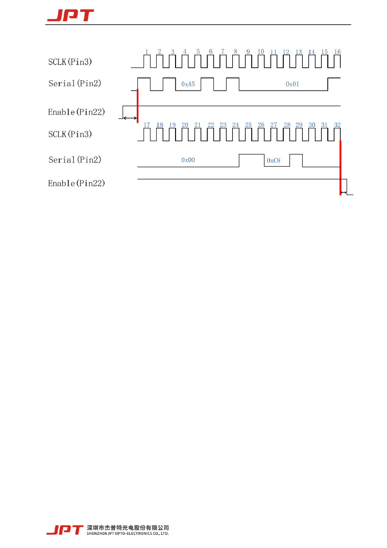
T2
Figure 13. Diagram of 200ns Pulse Width Control Sequence
T1: the duration is 10us, and the enabling signal of pulse width adjustment needs to be turned on
10us in advance before adjusting the serial input and the serial clock signal.
T2: the duration is 10us. After pulse width adjustment, it needs to delay 10us before closing.
➢ If the user sets 350ns pulse width, the input instruction is: 0xa5 → 0x01 → 0x01 → 0x5e,
where 0x01 and 0x5e represent the pulse width value 350.
➢ The parameter of this instruction is the binary value of pulse width.
➢ The user can compile any pulse width, but the laser only accepts the specified pulse width
(refer to the specifications of various versions for specific pulse width). If the given pulse
width is out of the range, the laser will output with the close pulse width value.
15
 JPT 200W 300W Pulsed Fiber Laser User Manual YDFLP-CL2 V0.1")
 JPT 200W 300W Pulsed Fiber Laser User Manual YDFLP-CL2 V0.1")
 JPT 200W 300W Pulsed Fiber Laser User Manual YDFLP-CL2 V0.1")
 JPT 200W 300W Pulsed Fiber Laser User Manual YDFLP-CL2 V0.1")
 JPT 200W 300W Pulsed Fiber Laser User Manual YDFLP-CL2 V0.1")
 JPT 200W 300W Pulsed Fiber Laser User Manual YDFLP-CL2 V0.1")
 JPT 200W 300W Pulsed Fiber Laser User Manual YDFLP-CL2 V0.1")
 JPT 200W 300W Pulsed Fiber Laser User Manual YDFLP-CL2 V0.1")
 JPT 200W 300W Pulsed Fiber Laser User Manual YDFLP-CL2 V0.1")
 JPT 200W 300W Pulsed Fiber Laser User Manual YDFLP-CL2 V0.1")
 JPT 200W 300W Pulsed Fiber Laser User Manual YDFLP-CL2 V0.1")
 JPT 200W 300W Pulsed Fiber Laser User Manual YDFLP-CL2 V0.1")
 JPT 200W 300W Pulsed Fiber Laser User Manual YDFLP-CL2 V0.1")
 JPT 200W 300W Pulsed Fiber Laser User Manual YDFLP-CL2 V0.1")
 JPT 200W 300W Pulsed Fiber Laser User Manual YDFLP-CL2 V0.1")
 JPT 200W 300W Pulsed Fiber Laser User Manual YDFLP-CL2 V0.1")
 JPT 200W 300W Pulsed Fiber Laser User Manual YDFLP-CL2 V0.1")
 JPT 200W 300W Pulsed Fiber Laser User Manual YDFLP-CL2 V0.1")
 JPT 200W 300W Pulsed Fiber Laser User Manual YDFLP-CL2 V0.1")
 JPT 200W 300W Pulsed Fiber Laser User Manual YDFLP-CL2 V0.1")
 JPT 200W 300W Pulsed Fiber Laser User Manual YDFLP-CL2 V0.1")
 JPT 200W 300W Pulsed Fiber Laser User Manual YDFLP-CL2 V0.1")
 JPT 200W 300W Pulsed Fiber Laser User Manual YDFLP-CL2 V0.1")
 JPT 200W 300W Pulsed Fiber Laser User Manual YDFLP-CL2 V0.1")
 JPT 200W 300W Pulsed Fiber Laser User Manual YDFLP-CL2 V0.1")
 JPT 200W 300W Pulsed Fiber Laser User Manual YDFLP-CL2 V0.1")
 JPT 200W 300W Pulsed Fiber Laser User Manual YDFLP-CL2 V0.1")
 JPT 200W 300W Pulsed Fiber Laser User Manual YDFLP-CL2 V0.1")
 JPT 200W 300W Pulsed Fiber Laser User Manual YDFLP-CL2 V0.1")
 JPT 200W 300W Pulsed Fiber Laser User Manual YDFLP-CL2 V0.1")
 JPT 200W 300W Pulsed Fiber Laser User Manual YDFLP-CL2 V0.1")
 JPT 200W 300W Pulsed Fiber Laser User Manual YDFLP-CL2 V0.1")