
YDFLP-CL2-200-1/5-A&YDFLP-CL2-300-1/5-A User Manual
2. Laser port definition
2.1 Power cord and interface installation
1) Fix the laser module onto the mounting panel, make sure enough air gap around
the laser module for sufficient air flow.
2) To connect the power supply cable to the 48V DC power supply, and make sure that
the DC power supply can provide enough output power. Please note the polarity of the cable.
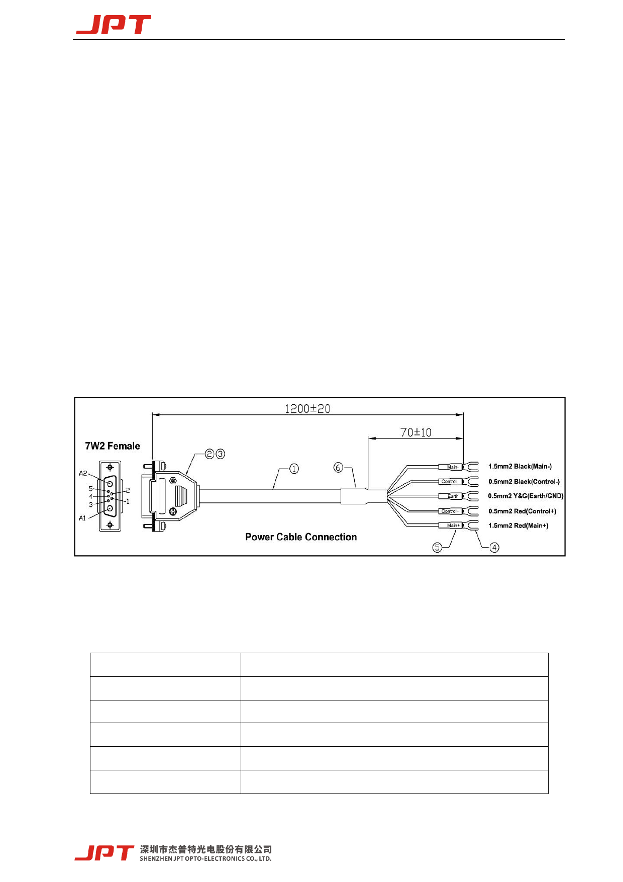
Power supply cable “+” is DC positive and “-” is DC negative and GND is ground wire.
Below figure8 is shown the power supply cable.
3) Ensure that the control interface of the external controller can match the laser,and then
connect the control cable to the laser and fix it.
Figure 7. YDFLP-CL2-200-1/5-A&YDFLP-CL2-300-1/5/10-A Schematic diagram of laser power
supply line
Table6. Laser power supply line pin definition
PIN
Describe
PE
Casing grounding wire
Main+
48VDC positive pole, laser main power supply
Main-
48VDC negative pole, laser main power supply
Control+
48VDC positive, control circuit power supply
Control-
48VDC negative, control circuit power supply
9
 JPT 200W 300W Pulsed Fiber Laser User Manual YDFLP-CL2 V0.1")
 JPT 200W 300W Pulsed Fiber Laser User Manual YDFLP-CL2 V0.1")
 JPT 200W 300W Pulsed Fiber Laser User Manual YDFLP-CL2 V0.1")
 JPT 200W 300W Pulsed Fiber Laser User Manual YDFLP-CL2 V0.1")
 JPT 200W 300W Pulsed Fiber Laser User Manual YDFLP-CL2 V0.1")
 JPT 200W 300W Pulsed Fiber Laser User Manual YDFLP-CL2 V0.1")
 JPT 200W 300W Pulsed Fiber Laser User Manual YDFLP-CL2 V0.1")
 JPT 200W 300W Pulsed Fiber Laser User Manual YDFLP-CL2 V0.1")
 JPT 200W 300W Pulsed Fiber Laser User Manual YDFLP-CL2 V0.1")
 JPT 200W 300W Pulsed Fiber Laser User Manual YDFLP-CL2 V0.1")
 JPT 200W 300W Pulsed Fiber Laser User Manual YDFLP-CL2 V0.1")
 JPT 200W 300W Pulsed Fiber Laser User Manual YDFLP-CL2 V0.1")
 JPT 200W 300W Pulsed Fiber Laser User Manual YDFLP-CL2 V0.1")
 JPT 200W 300W Pulsed Fiber Laser User Manual YDFLP-CL2 V0.1")
 JPT 200W 300W Pulsed Fiber Laser User Manual YDFLP-CL2 V0.1")
 JPT 200W 300W Pulsed Fiber Laser User Manual YDFLP-CL2 V0.1")
 JPT 200W 300W Pulsed Fiber Laser User Manual YDFLP-CL2 V0.1")
 JPT 200W 300W Pulsed Fiber Laser User Manual YDFLP-CL2 V0.1")
 JPT 200W 300W Pulsed Fiber Laser User Manual YDFLP-CL2 V0.1")
 JPT 200W 300W Pulsed Fiber Laser User Manual YDFLP-CL2 V0.1")
 JPT 200W 300W Pulsed Fiber Laser User Manual YDFLP-CL2 V0.1")
 JPT 200W 300W Pulsed Fiber Laser User Manual YDFLP-CL2 V0.1")
 JPT 200W 300W Pulsed Fiber Laser User Manual YDFLP-CL2 V0.1")
 JPT 200W 300W Pulsed Fiber Laser User Manual YDFLP-CL2 V0.1")
 JPT 200W 300W Pulsed Fiber Laser User Manual YDFLP-CL2 V0.1")
 JPT 200W 300W Pulsed Fiber Laser User Manual YDFLP-CL2 V0.1")
 JPT 200W 300W Pulsed Fiber Laser User Manual YDFLP-CL2 V0.1")
 JPT 200W 300W Pulsed Fiber Laser User Manual YDFLP-CL2 V0.1")
 JPT 200W 300W Pulsed Fiber Laser User Manual YDFLP-CL2 V0.1")
 JPT 200W 300W Pulsed Fiber Laser User Manual YDFLP-CL2 V0.1")
 JPT 200W 300W Pulsed Fiber Laser User Manual YDFLP-CL2 V0.1")
 JPT 200W 300W Pulsed Fiber Laser User Manual YDFLP-CL2 V0.1")