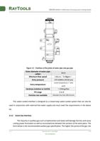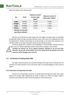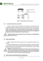
BM109 SERIES 1.5KW Auto-Focusing Laser Cutting Heads
screw the spring compression ring appropriately with force, and re-screw it into the collimating
components;
Lock the screws of the collimating components;
Check whether the focus position is in the center of the nozzle hole before use, if it is not in the
center, it is necessary to carry out center-regulating operation again.
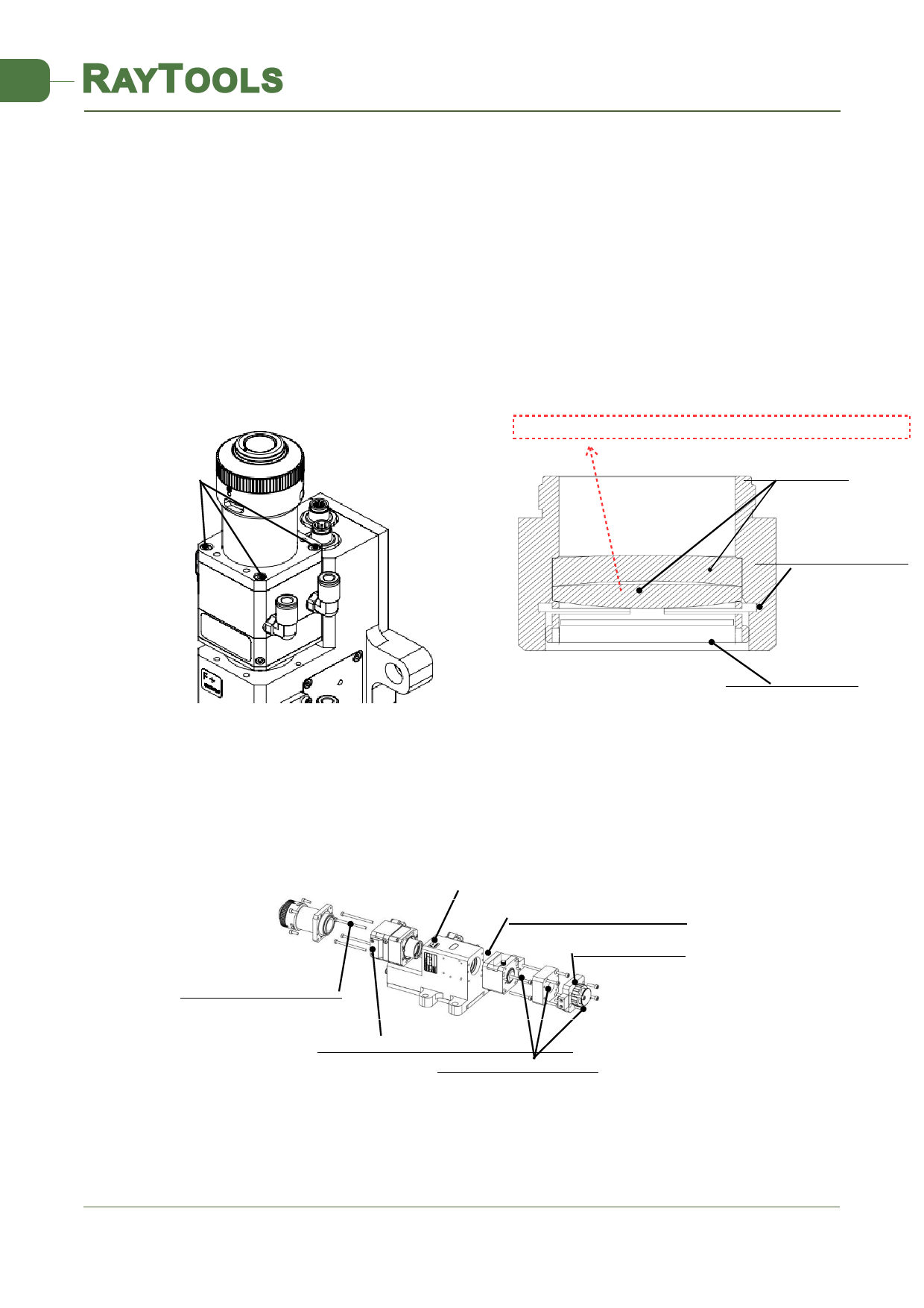
5.2.4 Removal and Installation of Focus Lenses
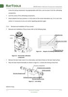
Removal and installation of focus lenses refer to the following steps.
Please note that biconvex lens gets 1 big curve face and 1 small curve face. The small curve face shall be next to
concave face of meniscus lens
Locking
screw
collimation lens
collimation lens holder
Elastic pressing ring
Figure 6.6 - Diagram of installing collimation lens
Figure 6.5 - Disassemble collimation
components
Remove the laser head, move it to a clean place, and clean all dust on the laser head surface;
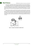
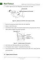
Place the laser head horizontally. As shown in Figure 6.7, remove the locking screws from
Focusing components
Protective mirror assembly
Nozzle assembly
M4 inner hexagon screw
Collimating water-cooled components
M4 inner hexagon screw
Figure 6.7 - Lens taking
bottom to top;
V1.0
RayTools AG © Copy Right
www.raytools.net
19 | 24


