BM109 SERIES 1.5KW Auto-Focusing Laser Cutting Heads
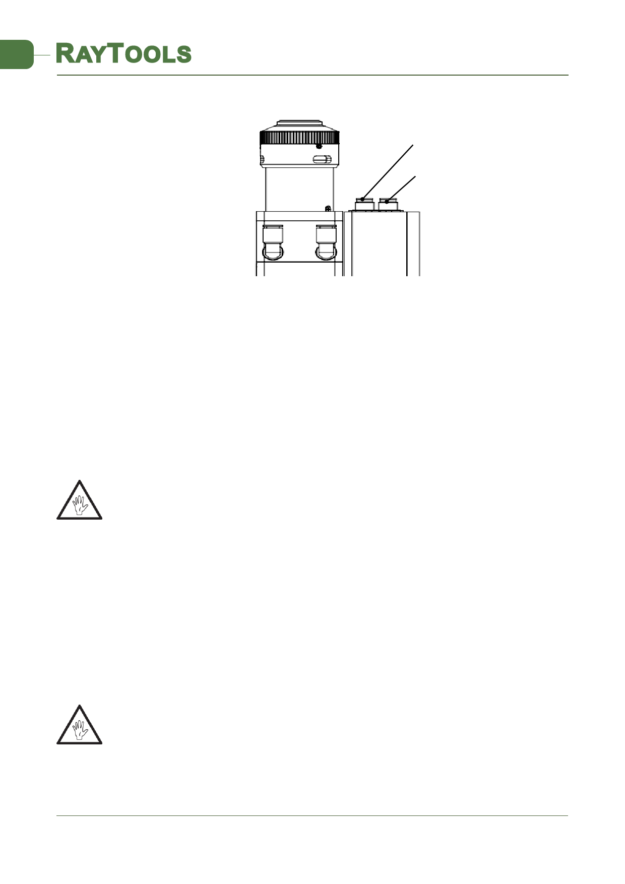
Eight-core male connector
Twelve-core male connector
Figure 3.3 - Cable interface of laser cutting head
2.3.2 Connection Cable and Driver Connection
Connect the eight-core power limit cable and the twelve-core encoder cable to the
corresponding interfaces on the drive as defined on the cable sleeve. For the wiring of the driver
and limit sensor cables, see the appendix for each series of system components - wiring diagram.
Caution: the limiting sensor is low-level normally closed output mode, and the two are
normally closed output mode (low level signal is output by the sensor when not triggered); if
necessary, the user should install relays for conversion in person.
CAUTION: All wiring is in the state of power failure, and the power can be debugged after
inspection without errors.
2.4 Fiber Input Interface
BM109 is suitable for most industrial laser generators. It is equipped with collimating mirror
assembly.
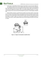
The connection between the end of the fiber and the cutting head is called fiber interface.
The commonly used fiber connector is QBH, and every fiber interface has its unique fixation
method. Please refer to the corresponding instruction of fibre-optical splice. Figure 3.4 shows
the installation interface of QBH connector.
WARNING: The optical devices must be kept clean and all dust must be removed before use. If
the laser head is vertically inserted in the optical fiber, the laser head must be rotated 90 degrees
to the horizontal level and then inserted into the optical fiber to prevent dust from falling on the
surface of the lens. Fix the laser head after inserting the optical fiber.
2.5 Fiber Insertion and Interface Direction Adjustment
V1.0
RayTools AG © Copy Right
9 | 24
www.raytools.net


