
RDC633xM Specification
Draw:
Drawing function is add lead in and lead out line manually. Click the button, the mouse is in edit status. Click on
any place in the graphical outline, the start point if the lead in/out line is set, and then click in arbitrary position
in the graphic outline, the software will add a lead in/out line automatically. Graphics must be selected before
perform this operation.
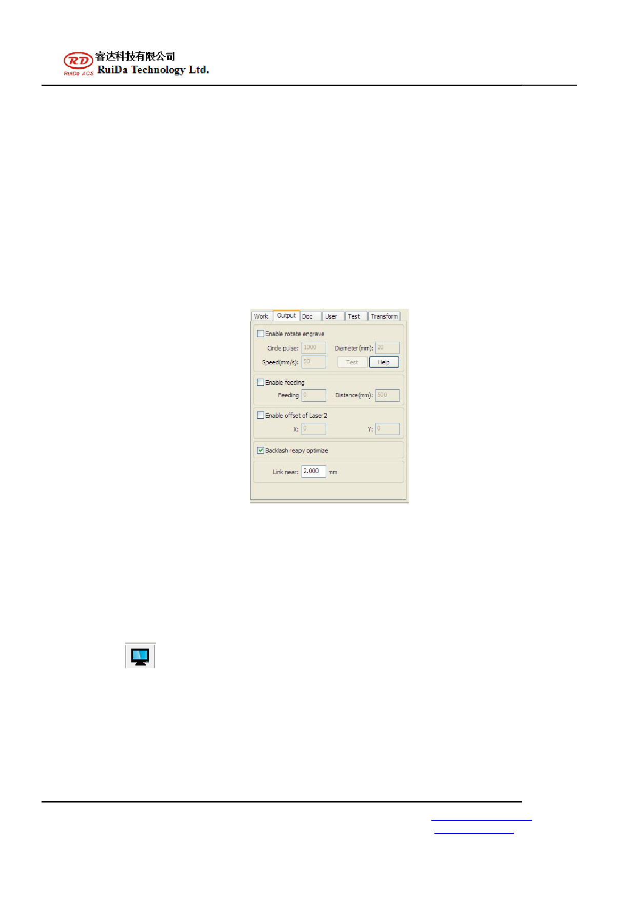
Add and delete small connection( link near):
After selected this icon, the system will set a small connection on the graphic outline automatically. This can
prevent the cut pieces falling down.
This link near length is in the menu "output" under "ling near" option, as shown in figure 4-3.
Figure 4-3 Micro Joints setting
Processing order setting:
After selected a graph unit, you can set the processing order manually. After the system import a graphic, will
default a processing order. Users can manually change the processing sequence number for each graph unit. When
graph unit is very long, the user can setting through the interface shown in figure 4-4, to meet the demand of the
processing direction. This interface is located in the "processing" of the “path optimization”. When using this
function, found that not according to the desired path processing, It could be because the value for partitioned
height setting is too big, to decrease the height appropriately, and test again. Can be observed through
“Simulation"
.
RuiDa Technology Co.,Ltd
1B,Building 5,Nanyou Tian’an Industry zone,Nanshan District,Shenzhen
TEL: 0755-26066687
E-Mail: support@rd-acs.com
Web: www.rd-acs.com
FAX: 0755-26982287
 RDC6332M Supplementary using manual")
 RDC6332M Supplementary using manual")
 RDC6332M Supplementary using manual")
 RDC6332M Supplementary using manual")
 RDC6332M Supplementary using manual")
 RDC6332M Supplementary using manual")
 RDC6332M Supplementary using manual")
 RDC6332M Supplementary using manual")
 RDC6332M Supplementary using manual")
 RDC6332M Supplementary using manual")
 RDC6332M Supplementary using manual")
 RDC6332M Supplementary using manual")
 RDC6332M Supplementary using manual")