BM115 SERIES 6-12KW Laser Cutting Head User Manual
CAUTION: Gas interface cannot be replaced arbitrarily, especially do not use PTFE TAPE,
Otherwise, the gas path will be blocked and cannot do normal cutting which will
damage cutting head at the same time.
2.3 Connection of Cutting Head Cable
2.3.1 Connection of Cutting Head and Cable
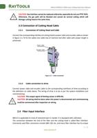
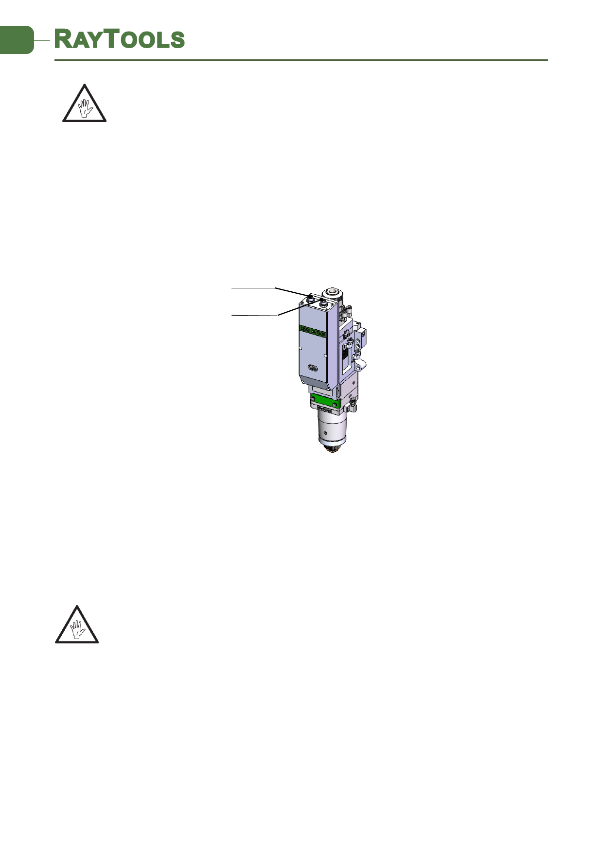
Connect the corresponding interface of cutting head to power cable and encoder cable as shown
in figure 2.3. To fix the cables into cable tray of machine tool after cable with proper length is
preserved.
Power cable
Encoder cable
Figure 2.3 — Cable connection
2.3.2 Cable connection to drive
Connect power cable and encoder cable to the corresponding interfaces of drive according to
the definition on cable sleeve. The wiring of drive is to be as per the system installation and
commissioning.
CAUTION: The output signal of limiting sensor is NPN-NC;
CAUTION: All wiring shall be done when the power is disconnected and commissioning
could be commenced after inspection on wiring.
.
2.4 Fiber Input Interface
BM115 is applicable to most of industrial laser in market. It is equipped with collimator.
The connection between the end of the fiber and the cutting head is called fiber interface.
Commonly used fiber connectors include QBH, QD, etc, and every fiber interface has its unique
www.raytools.ch
7 | 27


