BM115 SERIES 6-12KW Laser Cutting Head User Manual
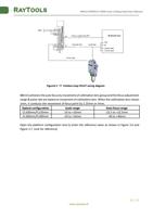
3.1.1 Interface & Signal
Interface
CON1
CON2
CON3
CON4
Descriptions
DB15 female connector, interface to servo driver.
Interface for connecting external IO devices.
Interface to 24V DC power supply.
Interface for connecting external IO devices.
Pins of CON1:
Pin
Descriptions
1
OUT_Servo_DA(Drive speed command)
2
Servo_TGON(Drive brake signal)
3
Servo_CLR(Drive alarm clear signal)
4
Servo_OS(Drive zero speed clamp, used to control motor lock
shaft)
5
PGND(Power ground)
6
E1_A_N(Encoder A negative)
7
E1_B_N(Encoder B negative)
8
E1_C_N(Encoder C negative)
9
AGND(Analog ground)
10
Servo_ALM(Drive alarm signal)
11
Servo_SON(Drive enable signal)
12
VDD_24V(Power supply)
13
E1_A_P(Encoder A positive)
14
E1_B_P(Encoder B positive)
15
E1_C_P(Encoder C positive)
Pins of CON2:
Pin
Descriptions
N/A
/
N/A
/
Alarm out When alarm occurs, a high level signal is output, normally is high
impedance state.
Home
Homing input signal, active high.
AGND
Common ground of analog signals, analog signals include: focus set
input, focus feedback output.
Focus set The input signal of focus setting, is analog.
www.raytools.ch
10 | 27


