1 Summary
BM115 SERIES 6-12KW Laser Cutting Head User Manual
1.1 Structure
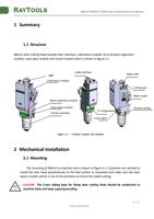
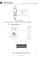
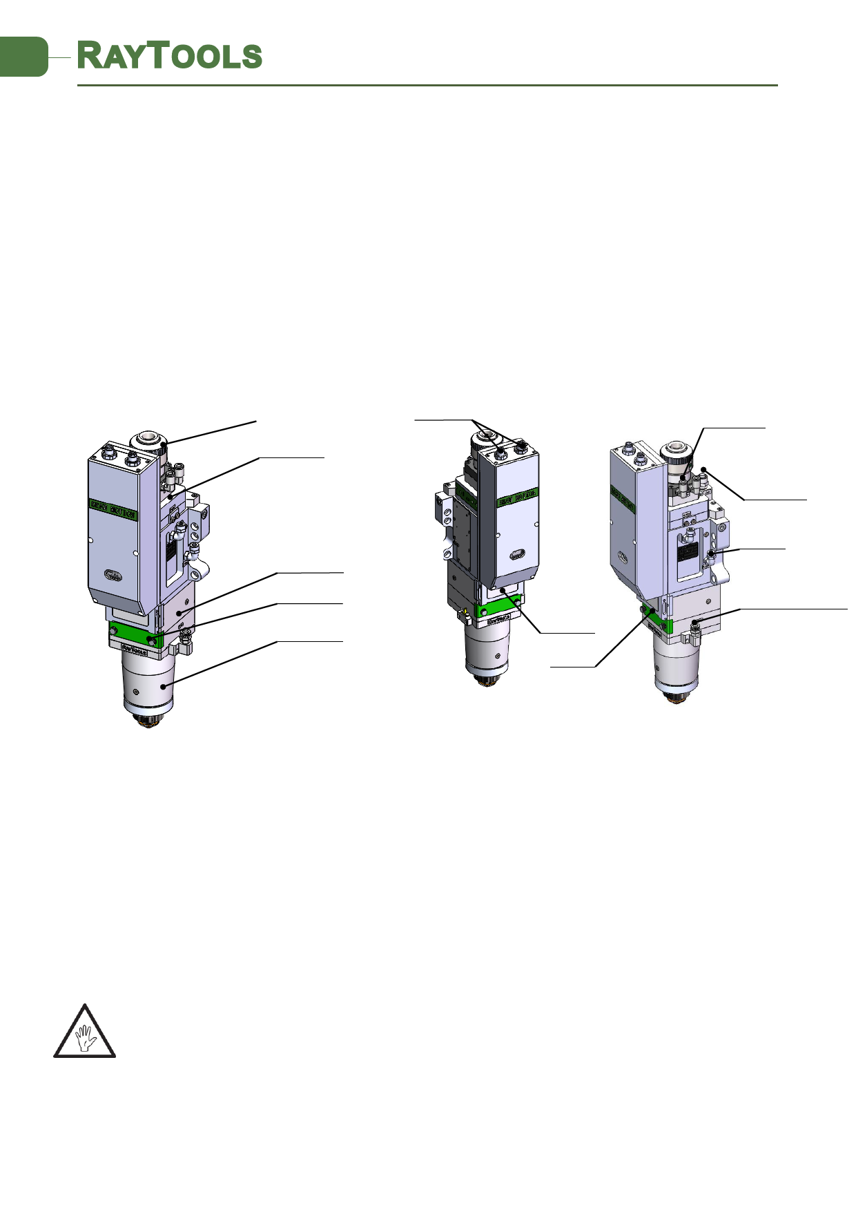
BM115 laser cutting head includes fiber interface, collimation module, focus & beam alignment
module, cover glass module and nozzle module which is shown in figure 1.1.
QBH
Collimation module
Cable interface
Beam alignment module
Cover glass module
Nozzle assembly
X-Y Adjustment
Cover glass
Water inlet
Cutting gas
Water outlet
Nozzle cooling
Figure 1.1 — Function module and interface
2 Mechanical Installation
2.1 Mounting
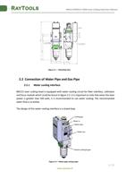
The mounting of BM115 to machine tool is shown in Figure 2.1. Customers are advised to
Install the laser head perpendicular to the bed surface as requested and make sure the laser
head is locked, which is one of the premises to ensure the stable cutting.
CAUTION: The Z-axis sliding base for fixing laser cutting head should be conductive to
machine tools and keep a good grounding.
www.raytools.ch
4 | 27

