Bandwidth Manager
The Bandwidth Manager allows you to adjust the bandwidth distribution of the connected cameras to avoid excessive packet losses so as to ensure data integrity. This is especially useful when multiple cameras use a same network interface for image acquisition.
-
All GigE Vision cameras produced by Hikrobot support bandwidth adjustment by Bandwidth Manager. You can also adjust bandwidth for GigE Vision cameras by setting the Gev SCPS Packet Size parameter and the Gev SCPD parameter. For details about the two parameters, see Transport Layer Control.
-
Part of the USB3 Vision cameras produced by Hikrobot support bandwidth adjustment by Bandwidth Manager. You can also adjust bandwidth for USB3 Vison cameras by setting the Device Link Throughput Limit Enable parameter and the Device Link Throughput Limit parameter. You can inquire our technical support for details about how to adjust bandwidth by the two parameters if your USB3 Vision camera supports the two parameters.
Make sure that the camera(s) whose bandwidth needs to be adjusted are not in acquisition and that their Trigger mode is turned off, and then click to open the Bandwidth Manager window.
You can click  to select the to-be-displayed
information (model name, device user ID, MAC address, etc.).
to select the to-be-displayed
information (model name, device user ID, MAC address, etc.).
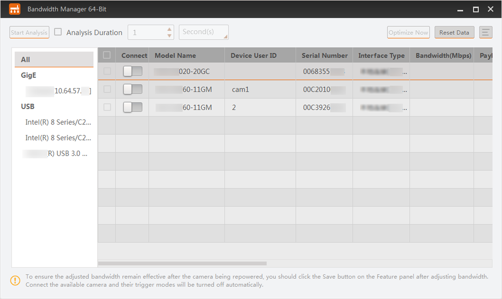 Figure 1 Bandwidth Manager Window
The list on the left shows the information of the GigE and USB interfaces on the PC.
-
If you select All, the camera list on the right will display all cameras under the GigE interfaces and USB interfaces.
-
If you select GigE, the camera list on the right will display all cameras under the GigE interfaces.
-
If you select USB, the camera list on the right will display all cameras under USB interfaces.
-
If you select a specific Interface, the camera list on the right will display all cameras under the selected interface.
Analysis before Optimization
After connecting camera(s), click Start Analysis to start analysis, and then click Stop Analysis to complete analyzing the bandwidth distribution of the cameras (you can also set the analysis duration to automatically stop analysis when the duration ends). And the value of payload received, frame sent, frame received, etc., will be displayed.
You can click Reset Data to reset the value of the above-mentioned parameters to 0.
|
Information Item |
Description |
|---|---|
|
Payload Sent (Mbps) |
The payloads that the camera sent to the PC during analysis. |
|
Payload Received (Mbps) |
The payloads that the camera received from the PC during analysis. |
|
Frame Sent (fps) |
The frames that the camera sent to the PC during analysis. |
|
Frame Received (fps) |
The frame that the camera received from the PC during analysis. |
|
Images |
The number of images that the PC received from the camera during analysis. |
|
Lost Packets |
The amount of packets that the PC failed to receive from the camera during analysis. |
|
Lost Frames |
The amount of the frames that the PC failed to receive from the camera during analysis. |
Bandwidth Optimization
Based on the analysis result, you can optimize bandwidth distribution of the connected cameras in the following two ways:
-
Select a GigE interface and then click Optimize Now to automatically optimize the bandwidth of the selected camera(s).
Note:Only GigE Vision cameras support the Optimize Now function.
-
Manually adjust the bandwidth, and then analyze again to view the changed value of payload received, frame sent, frame received, etc.
The less the payload losses and frame losses, the better the image quality would be.