
Wuhan Raycus Fiber Laser Technologies Co., Ltd.
User Guide of RFL- RFL-C3000S-CE
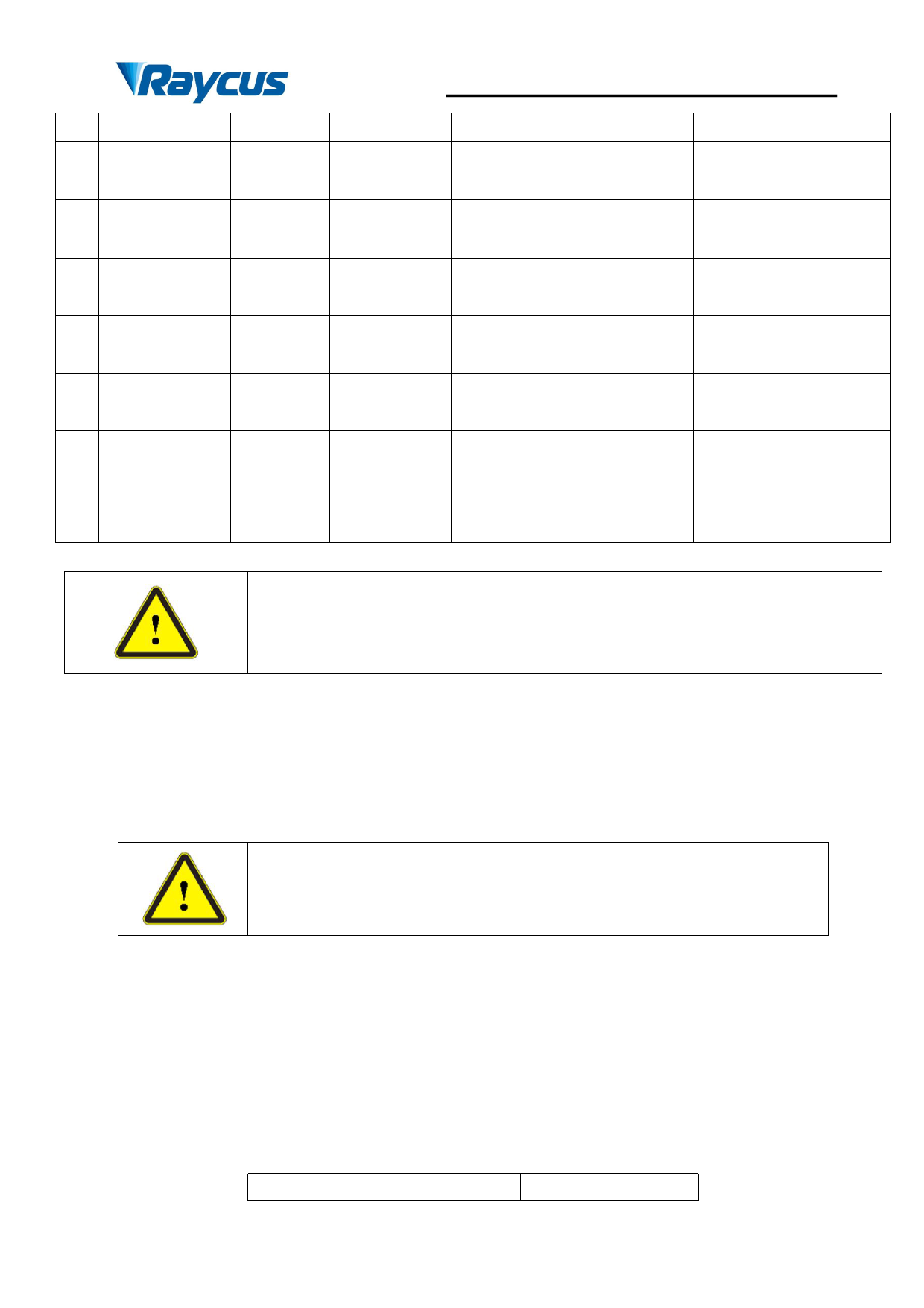
Control
Emission
18
Enable
19 READY
System
20
Common
21 Error RESET
22 Laser Alarm
23 Power started
ER
LAS-C
5-24Vd
Digital Input
C
READY Digital output 24VdC
GND2
Return
---
5-24Vd
RESET Digital Input
C
S-ERR Digital output 24VdC
POWER Digital output 24VdC
mA
<10
mA
>
10mA
---
<10
mA
>
10mA
>
10mA
120ms
emission in REM mode
Positive edge activates
emission in REM mode
120ms High=Laser is ready
---
120ms
Return for pin
17/18/19/21/22/23/24
Rising edge reset (the
resettable alarm)
120ms High=Alarm status
High= The main power
120ms
supply is started
24 Laser emission LASER Digital output 24VdC >10mA 100ms High=Laser is emission
Caution: Please check the control voltage level and ensure that the level is in
accordance with the requirements. Over voltage and voltage ripple may damage
the product.
The Service Security Interface is pin 1-4 and pin2-3, of CTRL-INTERFACE.If the pin 2-3
and pin 1-4 are disconnected, the laser will immediately stop emitting light, and the laser Ready
signal output will change to low level. Be sure to short-circuit pin 2-3 and pin 1-4 before using
the laser. If it is not short-circuited, the laser will display InterLock alarm after power-on.
Interlock interface must not be connected to active signal, otherwise it
will cause interface damage and laser alarm.
4.4.2 TCP/IP Interface Configuration
Thedefault IP address of this product is 192.168.0.10, only supporting UDP communication.
The laser listens for connection on port is 8098, and the command must be sent in a single data
string.
Table 8 Thepin definitions of Ethernet interface
PIN
FUNCTION
DESCRIPTION
23
 Raycus RFL-C3000S-CE Continuous-Wave Fiber Laser User Guide")
 Raycus RFL-C3000S-CE Continuous-Wave Fiber Laser User Guide")
 Raycus RFL-C3000S-CE Continuous-Wave Fiber Laser User Guide")
 Raycus RFL-C3000S-CE Continuous-Wave Fiber Laser User Guide")
 Raycus RFL-C3000S-CE Continuous-Wave Fiber Laser User Guide")
 Raycus RFL-C3000S-CE Continuous-Wave Fiber Laser User Guide")
 Raycus RFL-C3000S-CE Continuous-Wave Fiber Laser User Guide")
 Raycus RFL-C3000S-CE Continuous-Wave Fiber Laser User Guide")
 Raycus RFL-C3000S-CE Continuous-Wave Fiber Laser User Guide")
 Raycus RFL-C3000S-CE Continuous-Wave Fiber Laser User Guide")
 Raycus RFL-C3000S-CE Continuous-Wave Fiber Laser User Guide")
 Raycus RFL-C3000S-CE Continuous-Wave Fiber Laser User Guide")
 Raycus RFL-C3000S-CE Continuous-Wave Fiber Laser User Guide")
 Raycus RFL-C3000S-CE Continuous-Wave Fiber Laser User Guide")
 Raycus RFL-C3000S-CE Continuous-Wave Fiber Laser User Guide")
 Raycus RFL-C3000S-CE Continuous-Wave Fiber Laser User Guide")
 Raycus RFL-C3000S-CE Continuous-Wave Fiber Laser User Guide")
 Raycus RFL-C3000S-CE Continuous-Wave Fiber Laser User Guide")
 Raycus RFL-C3000S-CE Continuous-Wave Fiber Laser User Guide")
 Raycus RFL-C3000S-CE Continuous-Wave Fiber Laser User Guide")
 Raycus RFL-C3000S-CE Continuous-Wave Fiber Laser User Guide")
 Raycus RFL-C3000S-CE Continuous-Wave Fiber Laser User Guide")
 Raycus RFL-C3000S-CE Continuous-Wave Fiber Laser User Guide")
 Raycus RFL-C3000S-CE Continuous-Wave Fiber Laser User Guide")
 Raycus RFL-C3000S-CE Continuous-Wave Fiber Laser User Guide")
 Raycus RFL-C3000S-CE Continuous-Wave Fiber Laser User Guide")
 Raycus RFL-C3000S-CE Continuous-Wave Fiber Laser User Guide")
 Raycus RFL-C3000S-CE Continuous-Wave Fiber Laser User Guide")
 Raycus RFL-C3000S-CE Continuous-Wave Fiber Laser User Guide")
 Raycus RFL-C3000S-CE Continuous-Wave Fiber Laser User Guide")
 Raycus RFL-C3000S-CE Continuous-Wave Fiber Laser User Guide")
 Raycus RFL-C3000S-CE Continuous-Wave Fiber Laser User Guide")
 Raycus RFL-C3000S-CE Continuous-Wave Fiber Laser User Guide")
 Raycus RFL-C3000S-CE Continuous-Wave Fiber Laser User Guide")
 Raycus RFL-C3000S-CE Continuous-Wave Fiber Laser User Guide")
 Raycus RFL-C3000S-CE Continuous-Wave Fiber Laser User Guide")
 Raycus RFL-C3000S-CE Continuous-Wave Fiber Laser User Guide")
 Raycus RFL-C3000S-CE Continuous-Wave Fiber Laser User Guide")
 Raycus RFL-C3000S-CE Continuous-Wave Fiber Laser User Guide")
 Raycus RFL-C3000S-CE Continuous-Wave Fiber Laser User Guide")
 Raycus RFL-C3000S-CE Continuous-Wave Fiber Laser User Guide")
 Raycus RFL-C3000S-CE Continuous-Wave Fiber Laser User Guide")
 Raycus RFL-C3000S-CE Continuous-Wave Fiber Laser User Guide")
 Raycus RFL-C3000S-CE Continuous-Wave Fiber Laser User Guide")
 Raycus RFL-C3000S-CE Continuous-Wave Fiber Laser User Guide")
 Raycus RFL-C3000S-CE Continuous-Wave Fiber Laser User Guide")
 Raycus RFL-C3000S-CE Continuous-Wave Fiber Laser User Guide")
 Raycus RFL-C3000S-CE Continuous-Wave Fiber Laser User Guide")
 Raycus RFL-C3000S-CE Continuous-Wave Fiber Laser User Guide")
 Raycus RFL-C3000S-CE Continuous-Wave Fiber Laser User Guide")
 Raycus RFL-C3000S-CE Continuous-Wave Fiber Laser User Guide")
 Raycus RFL-C3000S-CE Continuous-Wave Fiber Laser User Guide")
 Raycus RFL-C3000S-CE Continuous-Wave Fiber Laser User Guide")
 Raycus RFL-C3000S-CE Continuous-Wave Fiber Laser User Guide")