5. Pulse Input Position Operation
5.1 Function Setting of Pulse Input Logic
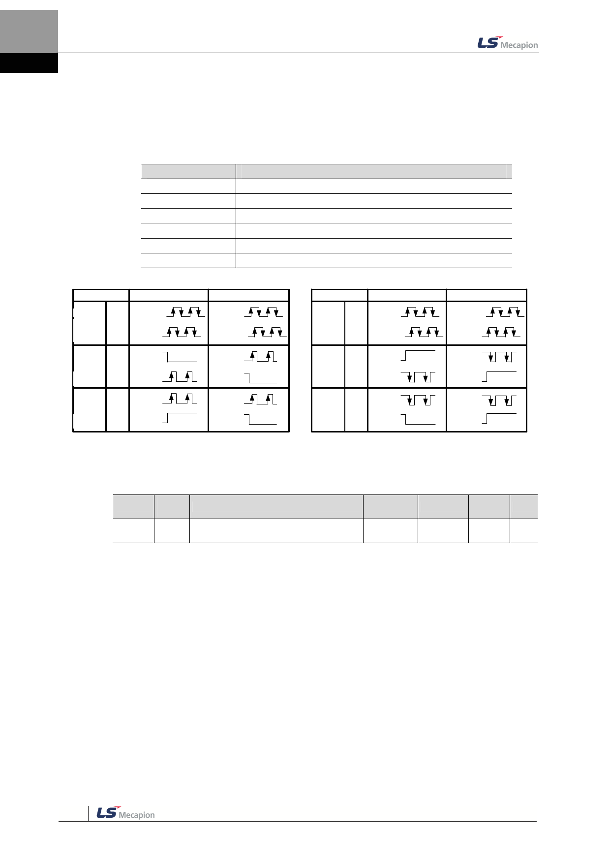
You can set the logic of the pulse strings from the host controller. The shapes of the input
pulses and the direction of rotation for each logic are as follows.
Set Values
0
1
2
3
4
5
Details
PHASE A+PHASE B,Positive Logic
CW+CCW,Positive Logic
Pulse+sign,Positive Logic
PHASE A+PHASE B,Negative Logic
CW+CCW,Negative Logic
Pulse+Sign,Negative Logic
PF + PR
PAh상ase A
+P+hBa상se B 0
p정os논itiv리e
logic
CW
+CCW 1
p정os논itiv리e
logic
Pulse+
direction
2
정polos논gitiicv리e
Forw정ard회ro전tation
PULS
(I/ O- 31)
SIGN
(I/ O- 33)
PULS
(I/ O- 31)
SIGN
(I/ O- 33)
L Level
PULS
(I/ O- 31)
SIGN
(I/ O- 33)
H Level
Rever역se회ro전tation
PULS
(I/ O- 31)
SIGN
(I/ O- 33)
PULS
(I/ O- 31)
SIGN
(I/ O- 33)
L Level
PULS
(I/ O- 31)
SIGN
(I/ O- 33)
L Level
PF + PR
PAh상ase A
++PhBa상se B 3
n부eg논ativ리e
logic
CW
+CCW 4
n부eg논ativ리e
logic
Pulse+
direction
5
부nelog논gaitci리ve
Forw정ar회d r전otation
PULS
(I/ O- 31)
SIGN
(I/ O- 33)
PULS
(I/ O- 31)
SIGN
(I/ O- 33)
H Level
PULS
(I/ O- 31)
SIGN
(I/ O- 33)
L Level
Rever역se회ro전tation
PULS
(I/ O- 31)
SIGN
(I/ O- 33)
PULS
(I/ O- 31)
SIGN
(I/ O- 33)
H Level
PULS
(I/ O- 31)
SIGN
(I/ O- 33)
H Level
Related Objects
Index
0x3003
Sub
Index
Name
- Pulse Input Logic Select
Variable
Format
UINT
Accessibility
PDO
Allocation
Unit
RW
No
-
5-2

