1. Product Composition
Contents
1
1. Product Composition......................................................................................... 1-6
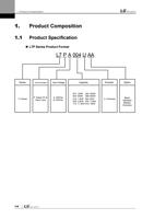
1.1 Product Specification..................................................................................................... 1-6
1.2 Names of Units .............................................................................................................. 1-8
1.2.1 Names of Servi Drive Units ............................................................................ 1-8
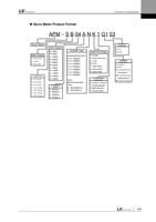
1.2.2 Names of Servo Motor Units ........................................................................ 1-11
1.3 Example of System Configuration ............................................................................... 1-12
2. Wiring and Connection ...................................................................................... 2-1
2.1 Servo Motor Installation ................................................................................................. 2-1
2.1.1 User Environment Requirement ..................................................................... 2-1
2.1.2 Preventing Excessive Impact.......................................................................... 2-1
2.1.3 Wiring with Motor............................................................................................ 2-1
2.1.4 Comibing with Load Device ............................................................................ 2-2
2.1.5 Cable Installation ............................................................................................ 2-2
2.2 Servo Driver Installation ................................................................................................ 2-3
2.2.1 Installation and User Environment .................................................................. 2-3
2.3 Drive Blocks .................................................................................................................. 2-4
2.3.1 Drive Blocks(100W ~ 400W) .......................................................................... 2-4
2.3.2 Drive Blocks (800W~3.5kW)........................................................................... 2-5
2.4 Power Unit Wiring.......................................................................................................... 2-6
2.4.1 Power Unit Wiring (100W~3.5kW) .................................................................. 2-7
2.4.2 Power Circuit Electronics Specifications......................................................... 2-8
2.5 Wiring of Input/Output Signal......................................................................................... 2-9
2.5.1 Names and Functions of Digital Input/Output Signals................................... 2-10
2.5.2 Names and Functions of Analog Input/Output Signals.................................. 2-15
2.5.3 Names and Functions of Pulse train Input Signals ....................................... 2-17
2.5.4 Names and Functions of Encoder Output Signals ........................................ 2-17
2.5.5 Example of Input/Output Signal Wiring ......................................................... 2-18
2.5.6 Purlse Train Input Signal .............................................................................. 2-22
2.5.7 Input/Output Signal Wiring............................................................................ 2-23
2.6 Encoder Signal Unit (Connector) Wiring ...................................................................... 2-24
2.6.1 Option Specifications Connection Example .................................................. 2-24
2.6.2 Linear Scale and Third party Encoder Connection Example......................... 2-29
3. L7P Indexer Overview ........................................................................................ 3-2
3.1 Control Methods ............................................................................................................ 3-2
3.2 Indexing Position Operation........................................................................................... 3-2
3.2.1 Coordinate Setting.......................................................................................... 3-7
3.2.2 Index Structure ............................................................................................... 3-9
3.3 Pulse Input Position Operation .................................................................................... 3-10
3.4 Velocity Control ............................................................................................................. 3-1
3.5 Torque Control ............................................................................................................... 3-4
1-1

