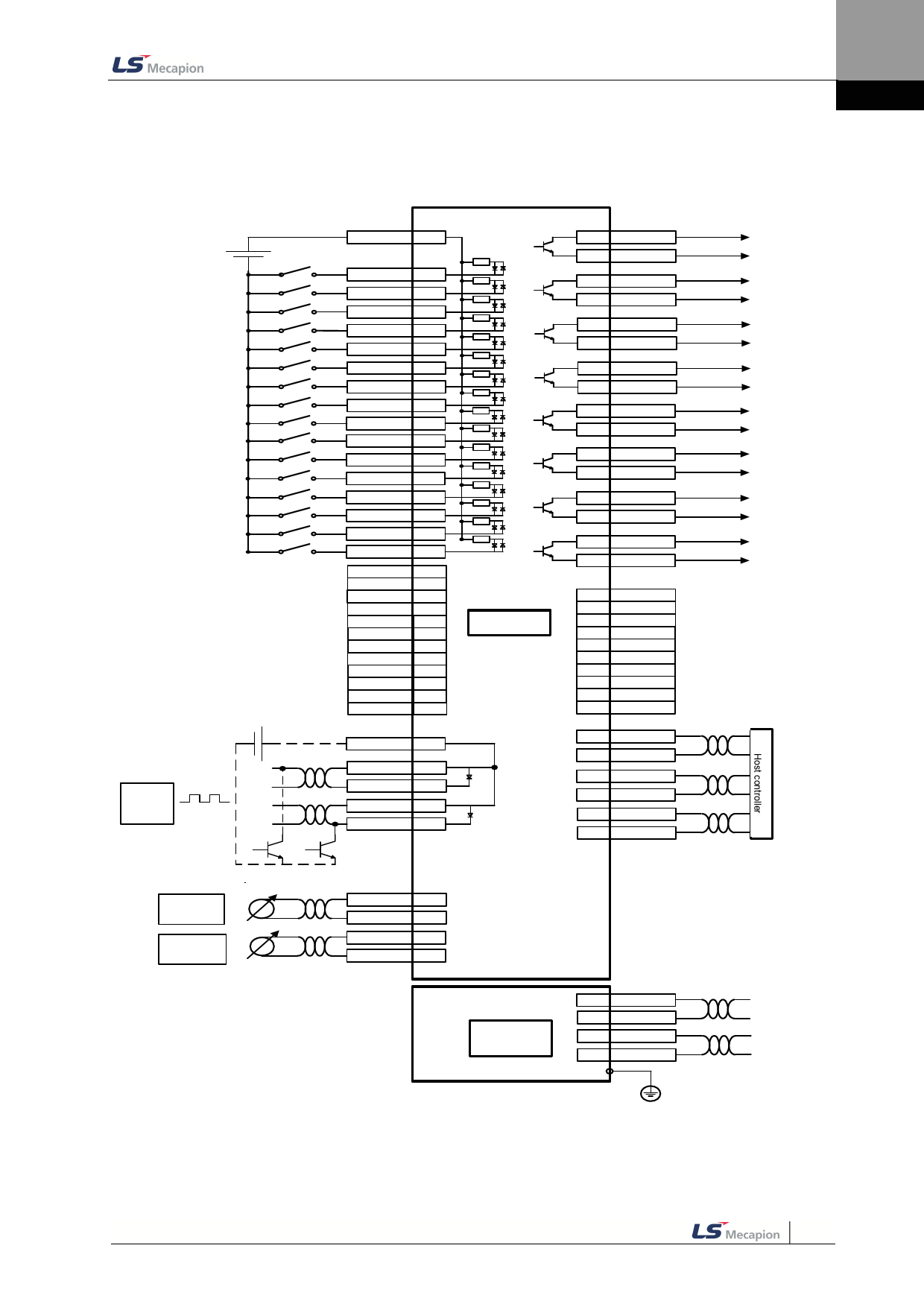
2. Wiring and Connection
2.5.7 Input/Output Signal Wiring
DC 24V
Command명Pu령ls펄 e I스 npu입 t 력
H상o위 st
c제 on어 tro기 lle
r
Analo아 g I날 np로 ut그 입력
아A날na로lo그 g
T토 orq크ue제L한 imit
AOn오 va아 el버 ror속 날 igd라e도 로S이p그e드ed
디 Di지 gita털l In입pu력t
+24V IN
21
SVON
12
POT
13
NOT
14
A-RST
15
START
16
STOP
17
RE GT
18
EMG
19
HOME
22
H-START
23
ISEL0
24
ISEL1
25
ISEL2
26
ISEL3
27
ISEL4
28
ISEL5
29
PCON
**
GAIN2
**
P CL
**
NCL
**
PROBE 1
**
PROBE2
**
P AU SE
**
ABS_RQ
**
JSTART
**
JDIR
**
PCLR
**
AOVR
**
PULCOM
30
PF+
31
PF-
32
라L인ine드D라 riv이 e 브
PR+
33
PR-
34
Op오en픈Co컬lle렉 cto터r
3.92kΩ
(DI1)
(DI2)
(DI3)
(DI4)
(DI5)
(DI6)
(DI7)
(DI8)
(DI9)
(DIA)
(DIB)
(DIC)
(DID)
(DIE)
(DIF)
(DI10)
I/O
(DO1) 35
36
(DO2) 37
38
(DO3) 39
40
(DO4) 41
42
(DO5) 43
44
(DO6) 45
46
(DO7) 47
48
(DO8) 49
50
Dig디 ita지 l O털 utp출 ut력
ALARM+
ALARM-
RDY+
RDY-
BRAKE+
BRAKE-
INPO S1+
INPO S1-
OR G+
OR G-
EOS+
EOS-
TGON+
TGON-
TLMT+
TLMT-
**
VLMT
**
INSPD
**
WAR N
**
INPO S2
**
IOUT0
**
IO UT1
**
IO UT2
**
IO UT3
**
IO UT4
**
IO UT5
E엔nc코od더er O출u력 tput
1
AO
2
/AO
상
3
BO
위
제
4
/BO
어
기
5
ZO
6
/ZO
-10V~+10V
A-TL MT
7
AGND
8
-10V~+10V
A-OV R
9
AGND
10
아날로그
An모 alog니Mo터 nitor
1 MONITOR 1
3
AGN D
2 MONITOR 2
4
AGN D
An아al날 og로O그 utp출 ut 력
-10V ~+10V
-10V ~+10V
Input signals DI1~DI10 and output signals DO1~DO8 are the signals allotted at the time of being
released from the factory.
Note) Digital output DO06, DP07 cannot be used as other functions when they are set encoder output
mode[0x3007] as line drive and open collector.
2-23

