2. Wiring and Connection
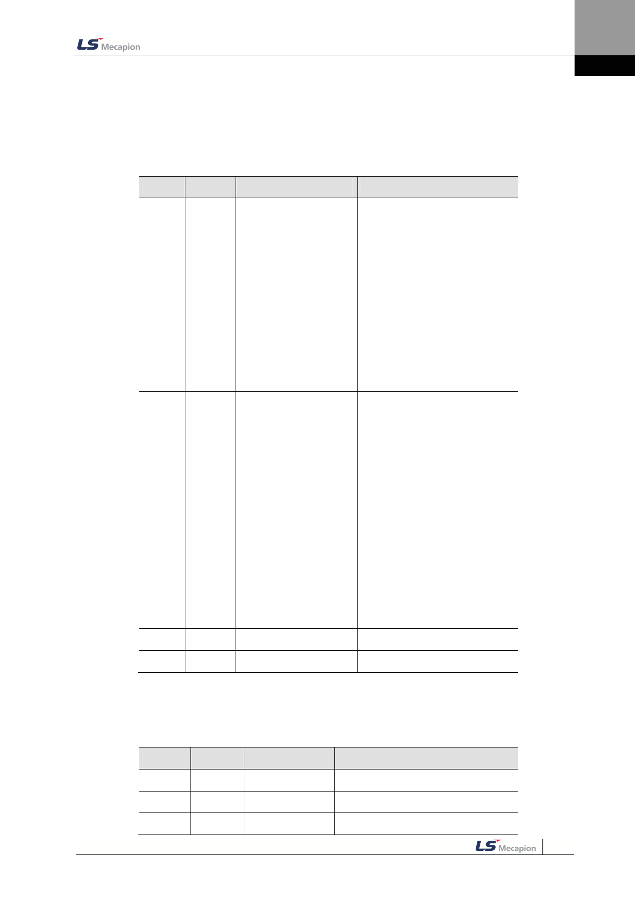
2.5.2 Names and Functions of Analog Input/Output
Signals
Names and Functions of Analog Input Signals (I/OConnector)
Pin No. Name
Description
Function Details
Index operation mode :
-10~+10V is connected between A-
TLMT(AI1) and AGND to limit the
motor’s output torque. The
relationship between input voltage
and torque limit varies depending
Analog Torque
on the set [0x221C] value.
7
A-TLMT Input(Command/ Limit)
Torque operation mode :
-10~+10V is connected between A-
TLMT(AI1) and AGND to operate
torque command. The relationship
between input voltage and torque
command varies depending on the
set [0x221C] value.
Index operation mode :
-10~+10Vis connected between A-
OVR(AI2)and AGND to override
index operation speed.
The override value is 0% under -
10Vinput, 100% under 0V input, and
200% under +10V input.You can
choose wether to use this function
9
A-OVR
Analog Speed
by [0x221E] or AVOR contact input.
Input(Command/Override)
Speed operation mode :
-10~+10Vis connected between A-
OVR(AI2)and AGND to operate
Analog speed mode.
The relationship between input
voltage and speed command varies
depending on the set [0x2229]
value.
8
AGND
AGND(0V)
Analog ground
10
AGND
AGND(0V)
Analog ground
Names and Functions of Analog Output Signals(Analog Monitoring
Connector)
Pin No.
1
2
3
Name
AMON1
AMON2
AGND
Description
Function Details
Analog monitor 1 Analog monitoroutput(-10V ~ +10V)
Analog monitor 2 Analog monitoroutput(-10V ~ +10V)
AGND(0V)
Analog ground
2-15

