2. Wiring and Connection
2-14
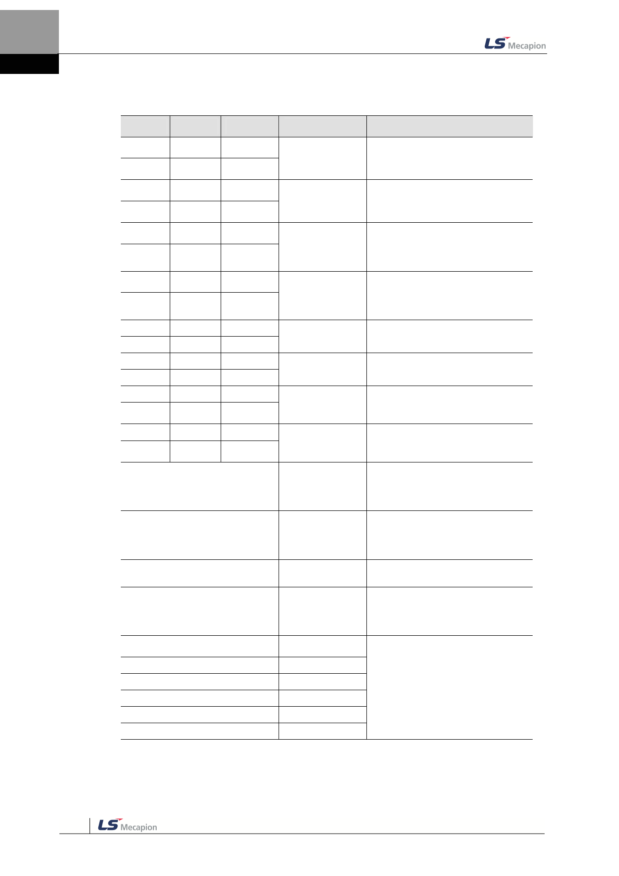
Names and Functions of Digital Input Signals(I/OConnector)
Pin No. Name Allotment Description
Function Details
35
36
DO1+
DO1-
ALARM+
ALARM-
Servo alarm
This signal is displayed when the
servo alarm sets off.
37
DO2+
RDY+
38
DO2-
RDY-
Servoready
This signal is displayed when the main
power is on and the servo is
operational.
39
DO3+ BRAKE+
40
DO3-
BRAKE-
Brake
This signal is for controlling brakes
installed inside or outside the motor. It
is displayed when the SVON contact
is off.
41
DO4+ INPOS1+
This signal is displayedwhen the
Position reached command position is reached.You can
42
DO4-
INPOS1-
1
set the display conditions by adjusting
the [0x2401], [0x2402] values.
43
DO5+
ORG+
Origianl position This signal is displayed whenorigin
44
DO5-
ORG-
reached
operation is complete.
45
DO6+
EOS+
46
DO6-
EOS-
Operation
complete
This signal is displayed when index
operation is complete.
47
DO7+
TGON+
This signal is displayed when the
Rotation detection motor rotates faster than the set
48
DO7-
TGON-
[0x2405] value.
49
DO8+
TLMT+
50
DO8-
TLMT-
Torque limit
This signal is displayed when the drive
output is limited within the set torque
limit value.
** VLMT
Speed limit
This signal is displayed when the
motor reaches the speed limit. The
speed limit can be adjusted by setting
the [0x230D], [0x230E] values.
** INSPD
Speed reached
This signal is displayed when the
difference between the command
speed and the current speed is under
the set [0x2406]value.
** WARN
Servo warning
This signal is displayed when a
warning sets off.
** INPOS2
Position reached
2
This signal is displayedwhen the
command position is reached.You can
set the display conditions by adjusting
the [0x2401], [0x2402] values.
** IOUT0
Index output0
** IOUT1
** IOUT2
** IOUT3
** IOUT4
** IOUT5
Index output1
Index output2
Index output3
Index output4
Index output5
This signal displays the number of the
index currently prformed (0~63)
**These signals are not allotted at the time of the product’s release from the factory. You can
change allotment by configuring the parameters. Please see 「10.2 Input/Output Signal Setting」 for
further details.

