12. Communication Protocol
Note 2)The servo drive’s IN/OUT connectorpins are internally connected 1 to 1, allowing for convenient
multi-drop wiring.
15.1.2 Comunication Specifications and Connection
Diagram
Communication Specifications
Item
Specifications
Communication Standard ANSI/TIA/EIA-422 Standard
Communication Protocol MODBUS-RTU
Data
Type
Data bit
Stop bit
Parity
8bit
1bit
None
Syncrho
Asyncrhonous method
Transmission Speed
9600 /19200/38400/57600 [bps]
Speed can be selected at communication
spped setting [0x3002]
Transmission Distance Up to 200 [m]
Power Consumption
Under 100[㎃]
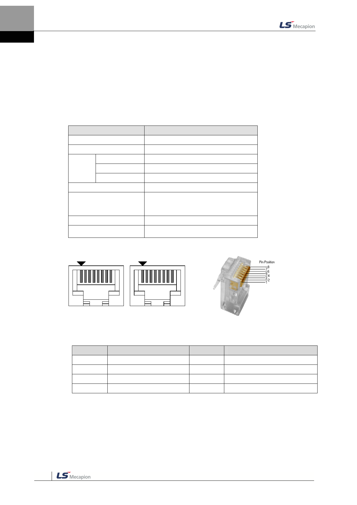
RS-422 communication connectorpin connection
1
8
1
8
OUT
IN
Pin arrangement viewed from the front
side of the drive
Pin arrangement viewed from the
connector
Pin No.
1
2
3
4
Pin Function
Not Used
Not Used
RXD+
TXD-
Pin No.
5
6
7
8
Pin Function
TXD+
RXD-
Not UsedNote 1)
Not UsedNote 1)
Note 3)As for INconnector, 5V voltage is output to Pin No. 7 and Pin No. 8, to supply power to the handy
loader. Use for any other purpose is not allowed, and do not connect Pin No. 7 and Pin No.
8 when wiring.
Note 4)Connect TXD+ and TXD-, RXD+ and RXD- using twisted pair
Note 5)TXD and RXD of the above table is defined based on the servo drive.
15-2

