2. Wiring and Connection
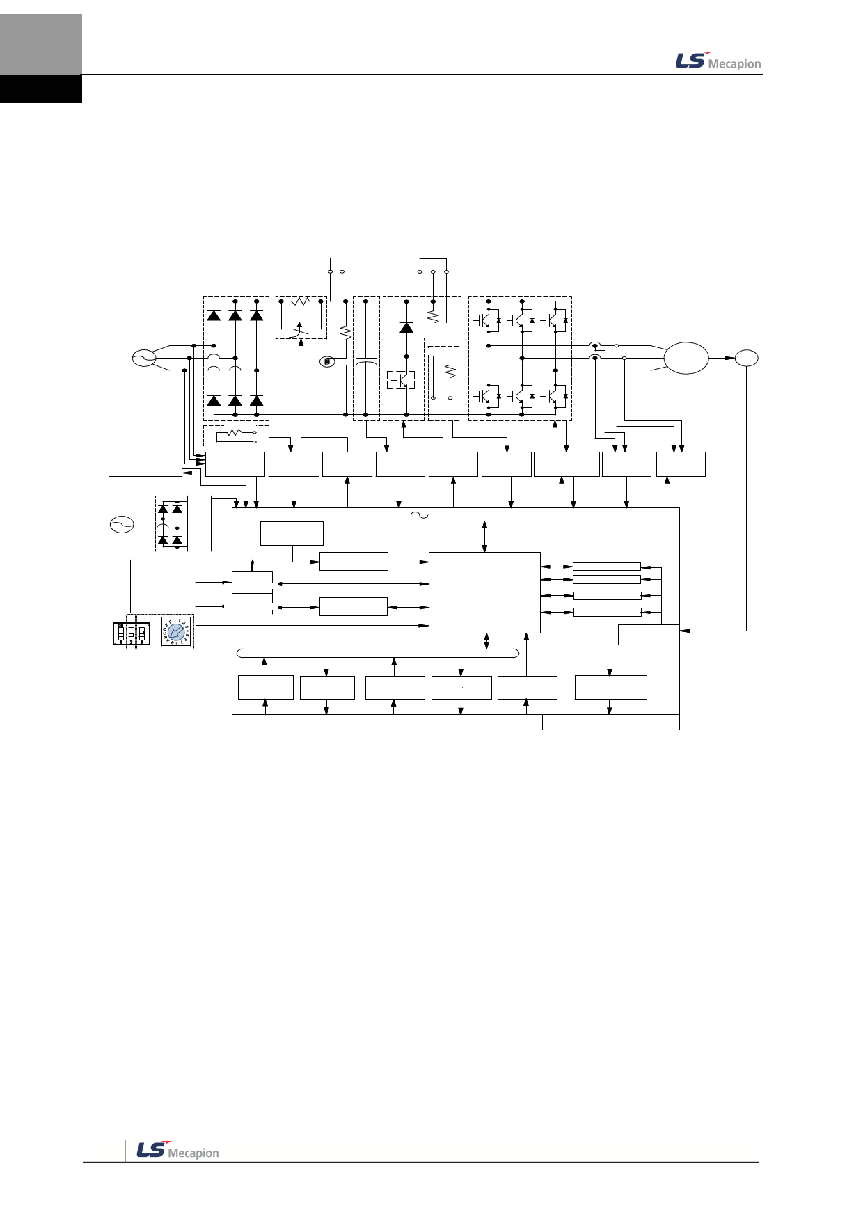
2.3 Drive Blocks
2.3.1 Drive Blocks(100W ~ 400W)
Diode
Note 1주) 1) PO
PI
the써rm미is스to터r
B
B+ BI N주ot2e) 2)
IGBT
3-p3h상as전e 원power입in력put
AC200~230V
L1
L2
L3
th써erm미is스tor터
Chage
Lamp
recovery
res회ista생nc저e 항
th써er미mis스to터r
T1 T2
cr전uu류ent센se서nsor
U
V
M
E
W
제어전원결상
con검tro출l 회po로wer
single단-ph상ase전p원ower i입npu력t
AC200~230V
C1
C2
Terminal
종re단sis저ta항nce
설sw정itc스h위치
0
주전원결상
con검tr출ol 회po로wer
내부온도
검In출n회er.로
Relay
re구la동y 회dri로ve
DC전압
D검C 출vo회lta로ge
re회cov생er제y b동rake
d구riv동e c회irc로uit
IGBIGTB온T도
temp.detection
검c출irc회uit로
S
M
mMaianinco제nt어rol
P
S
U,UV,VC전u류rrent
DCD전C압
RS-422
IN / OUT RS 422
Comm통un신ication
USB
USB
Comm통un신ication
A/D AC/oDnv변er환sion
USB OTG FS
POWpoEwRe회r c로irc접uit속
MCU / FPGA
n노o드de주소
a설d정dr스es위s치
switch
P/CP/C절In연sulIa/tFion I/F
PWPWM Msig신na호l SC
dSetCec검tio출n c회irc로uit
U,UV,VC전urr류ent
Det검ect출ion회C로ircuit
DB
DB구dri동ve회cir로cuit
BiSS-C
Quadrature
TAMAGAWA
EnDat
Encoder input
(Encoder connector)
펄pu스lse입in력put
(2점)
엔enc코od더er o출ut력put
(3점)
디dig지it털al 입inp력ut
(16점)
d디ig지ita털l o출ut력put
(8점)
아an날a로log그in입pu력t
(2점)
a아na날lo로g 그ou출tp력ut
(2점)
host con상tro위ll제er어c기on연ne결c(tIi/oOn) (I/O)
상위제어h(기aonsat연lcoog결notr(uo아tlpleu날rt cc로oonn그nneecc출ttioorn력) 커넥터)
Note 1)When using DC reactor, please connect with PO, PI.
Note 2)When using external recovery resistance, remove the shorting pins B, BI and then connect with
the B+, B pins.
2-4

