10. Application Functions
10.12 Encoder Signal Output
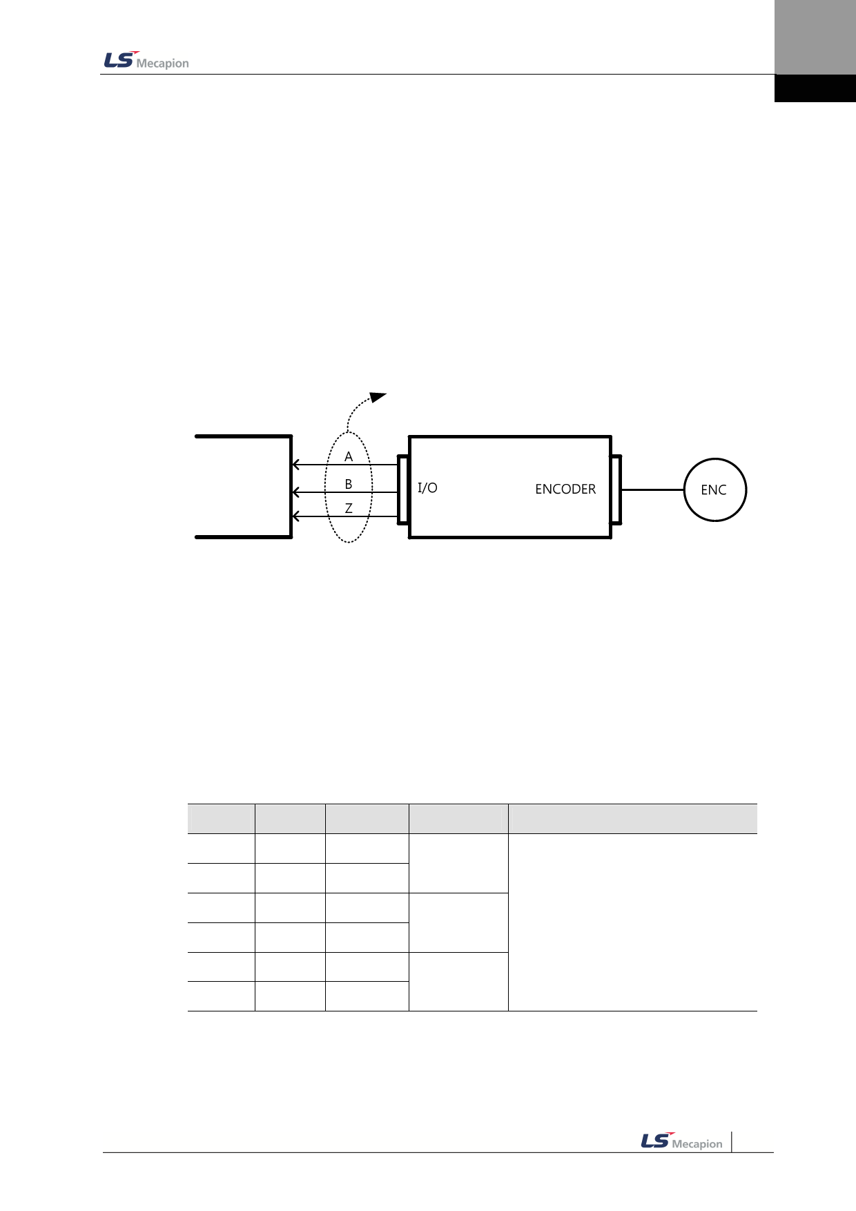
The drive internally processes the signal from the encoder, and outputs them in the form of
pulses. The pulses are output using the line drive method through the pins allocated by
default to the I/O connector (1~6). The pulses can be output using the open collecter method
depending on the setting of the encoder output mode [0x3007].
Output using the open collector method uses the DO06 (PHASE A), DO07 (PHASE B),
DO08(PHASE B) ports allocated by defulat to digital output signal, masking the
corresponding output function.
You can set the number of encoder pulses ouput per 1 rotation with the encoder output pulse
[0x3006] value.
Host controller
Encoder output
Servo drive
The encoder signal output frequency of the drive is up to 200 [Kpps] when using the open
collector method, and up to 2.0 [Mpps] when using the line drive method.
The motor rotational speed is limited depending on the set value of number of encoder
output pulses per rotation: therefore, an appropriate value should be set.
Example) when outputting 50000[ppr] using the line drive method, up to 2400[rpm] can be
achieved.
2400[rpm] = 2*106 / 50000 * 60
Encoder Output Signal of the Line Drive Method
Pin No.
1
2
3
4
5
6
Name
AO
/AO
BO
/BO
ZO
/ZO
Allocation Description
Details
-
Encoder
-
Signal A
-
-
Encoder
Signal B
Outputs divded encoder signals (Phase
A, B, Z) using the line drive method.The
output division can be set at [0x3006].
-
Encoder
-
Signal Z
10-43

