10. Application Functions
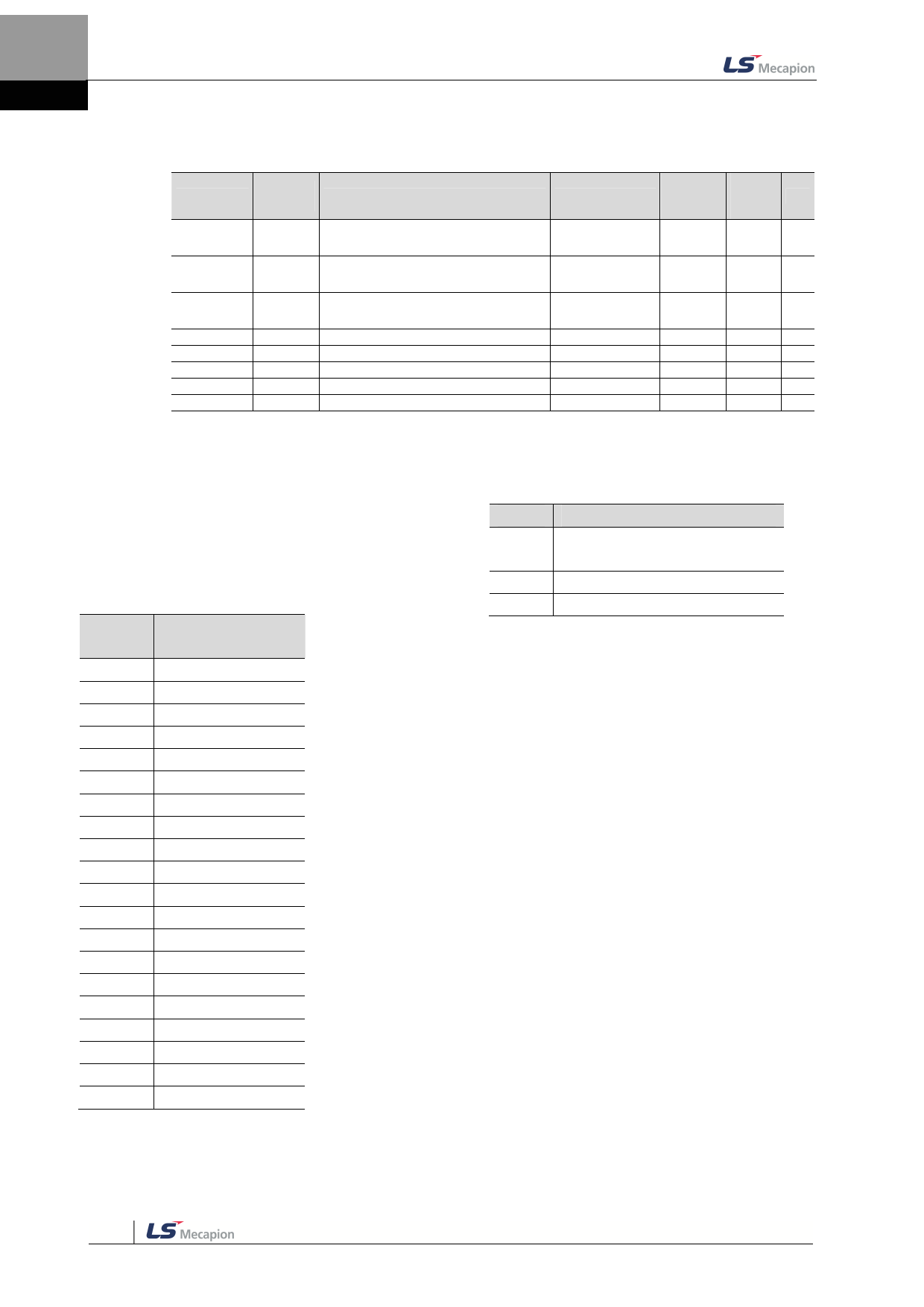
Related Objects
Index
0x2210
0x2211
0x2212
0x2213
0x2214
0x2215
0x2216
0x2217
Sub
Index
Name
-
Digital Output Signal 1 Selection
-
Digital Output Signal 2 Selection
-
Digital Output Signal 3 Selection
-
Digital Output Signal 4 Selection
-
Digital Output Signal 4 Selection
-
Digital Output Signal 4 Selection
-
Digital Output Signal 4 Selection
-
Digital Output Signal 4 Selection
Variable Format
Accessibil
ity
PDO
Allocati
on
Unit
UINT
RW
-
UINT
RW
-
UINT
RW
-
UINT
RW
-
UINT
RW
-
UINT
RW
-
UINT
RW
-
UINT
RW
-
You can set the output signal level by allocating functions of
diginal output signals of I/O connector. Choose the signals to
allocate with bit 7~0, and set the signal level at bit 15.
Set
Value
0x00
0x01
0x02
0x03
0x04
0x05
0x06
0x07
0x08
0x09
0x0A
0x0B
0x10
0x11
0x12
0x13
0x14
0x15
0x16
0x17
Allocatable Output
Signals
Not Allocated
BRAKE
ALARM
RDY
ZSPD
INPOS1
TLMT
VLMT
INSPD
WARN
TGON
INPOS2
ORG
EOS
IOUT0
IOUT1
IOUT2
IOUT3
IOUT4
IOUT5
Bit
15
14~8
7~0
Details
Signal output level setting
(0:CONTACT A, 1:CONTACT B)
Reserved
Allocated output signal
10-12

